
Page 396 - The Mechatronics Handbook
P. 396
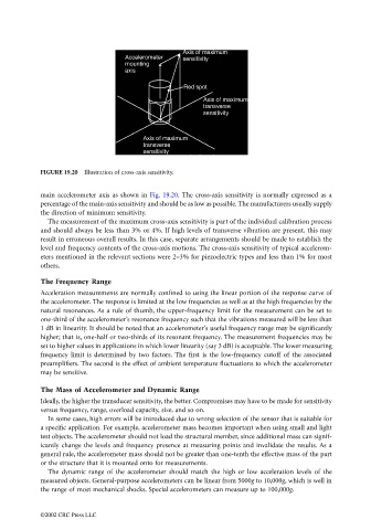
FIGURE 19.20  Illustration of cross-axis sensitivity.


                                 main accelerometer axis as shown in  Fig. 19.20. The cross-axis sensitivity is normally expressed as a
                                 percentage of the main-axis sensitivity and should be as low as possible. The manufacturers usually supply
                                 the direction of minimum sensitivity.
                                   The measurement of the maximum cross-axis sensitivity is part of the individual calibration process
                                 and should always be less than 3% or 4%. If high levels of transverse vibration are present, this may
                                 result in erroneous overall results. In this case, separate arrangements should be made to establish the
                                 level and frequency contents of the cross-axis motions. The cross-axis sensitivity of typical accelerom-
                                 eters mentioned in the relevant sections were 2–3% for piezoelectric types and less than 1% for most
                                 others.
                                 The Frequency Range
                                 Acceleration measurements are normally confined to using the linear portion of the response curve of
                                 the accelerometer. The response is limited at the low frequencies as well as at the high frequencies by the
                                 natural resonances. As a rule of thumb, the upper-frequency limit for the measurement can be set to
                                 one-third of the accelerometer’s resonance frequency such that the vibrations measured will be less than
                                 1 dB in linearity. It should be noted that an accelerometer’s useful frequency range may be significantly
                                 higher; that is, one-half or two-thirds of its resonant frequency. The measurement frequencies may be
                                 set to higher values in applications in which lower linearity (say 3 dB) is acceptable. The lower measuring
                                 frequency limit is determined by two factors. The first is the low-frequency cutoff of the associated
                                 preamplifiers. The second is the effect of ambient temperature fluctuations to which the accelerometer
                                 may be sensitive.

                                 The Mass of Accelerometer and Dynamic Range
                                 Ideally, the higher the transducer sensitivity, the better. Compromises may have to be made for sensitivity
                                 versus frequency, range, overload capacity, size, and so on.
                                   In some cases, high errors will be introduced due to wrong selection of the sensor that is suitable for
                                 a specific application. For example, accelerometer mass becomes important when using small and light
                                 test objects. The accelerometer should not load the structural member, since additional mass can signif-
                                 icantly change the levels and frequency presence at measuring points and invalidate the results. As a
                                 general rule, the accelerometer mass should not be greater than one-tenth the effective mass of the part
                                 or the structure that it is mounted onto for measurements.
                                   The dynamic range of the accelerometer should match the high or low acceleration levels of the
                                 measured objects. General-purpose accelerometers can be linear from 5000g to 10,000g, which is well in
                                 the range of most mechanical shocks. Special accelerometers can measure up to 100,000g.


                                 ©2002 CRC Press LLC