
Page 392 - The Mechatronics Handbook
P. 392
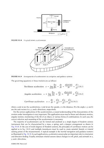
FIGURE 19.18  A typical seismic accelerometer.


                                                           Accel Z                   Computer and
                                                         Gyro X                     signal processing


                                                                                Gyro Z
                                                                             Accel X

                                                         Gyro Y  Accel Y


                                 FIGURE 19.19  Arrangements of accelerometers in navigation and guidance systems.

                                 The governing equations of these motions are as follows:
                                                                                                 2
                                                                                       (
                                                                          Dv    dv   dds/dt)    d s
                                              Rectilinear acceleration a =  lim  -------  =  -----  =  ---------------------  =  ------- 2 (19.1)
                                                                       DtÆ0  Dt  dt     dt      dt
                                                                                                2
                                                                                      (
                                                                         Dw    dw    ddq/dt)   d q
                                              Angular acceleration a =  lim  --------  =  -------  =  ----------------------  =  -------- 2 (19.2)
                                                                               dt
                                                                                        dt
                                                                     DtÆ0  Dt                   dt
                                                                                          2
                                                                                    2
                                                                              2
                                                                        dv   d x   d y   d z
                                              Curvilinear acceleration  a =  -----  =  -------- 2 i +  ------- 2 j +  ------- 2 k (19.3)
                                                                        dt   dt    dt    dt
                                 where a and α are the accelerations; v and ω are the speeds; s is the distance; θ is the angle; i, j, and k
                                 are the unit vectors in x, y, and z directions, respectively.
                                   For the correct applications of the accelerometers, a sound understanding of the characteristics of the
                                 motion under investigation is very important. The application areas may be linear and vibratory motion,
                                 angular motion, monitoring of the tilt of an object, or various forms of combinations. In each case, the
                                 correct selection and mounting of the accelerometer is necessary.
                                   The majority of accelerometers can be viewed and analyzed as a single-degree-of-freedom seismic
                                 instrument that can be characterized by a mass, a spring, and a damper arrangement as shown in
                                 Fig. 19.18. In the case of multi-degrees-of-freedom systems, the principles of curvilinear motion can be
                                 applied as in Eq. (19.3) and multiple transducers must be used to create uniaxial, biaxial, or triaxial
                                 sensing points of the measurements. A typical example is the inertial navigation and guidance systems
                                 as illustrated in Fig. 19.19. In such applications, acceleration sensors play an important role in orientation
                                 and direction finding. Usually, miniature triaxial sensors detect changes in roll, pitch, and azimuth in x,
                                 y, and z directions.

                                 ©2002 CRC Press LLC