
Page 388 - The Mechatronics Handbook
P. 388
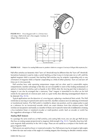
FIGURE 19.14  Detecting gear teeth in a ferrous mate-
                                 rial using a Hall switch and a bias magnet. Courtesy of
                                 Allegro Microsystems, Inc.


                                 FIGURE 19.15  Output of an analog Hall sensor vs. position relative to a magnet. Courtesy of Allegro Microsystems, Inc.

                                 Hall effect switches are hysteretic: their “turn-on” threshold may be different than the “turn-off” threshold.
                                 Sometimes hysteresis is used to make a switch latching, so that it stays in its last state (on or off) until the
                                 applied magnetic field is reversed. Non-latching Hall switches may be unipolar (responding only to one
                                 orientation of magnetic field) or bipolar (responding to a field of either polarity). Turn-on and turn-off
                                 times are in microseconds.
                                   Hall switches have wide operating temperature ranges and are often used in automobile engine
                                 compartments. Another advantage is that they are not susceptible to most of the fouling mechanisms of
                                 optical or mechanical switches, such as liquids or dirt. While often the moving part that is detected is a
                                 magnet, it can also be arranged that a stationary “bias” magnet is intensified in its effect on the hall
                                 switch by the approach of a ferrous part, such as a gear tooth, thus allowing nonmagnetized objects to
                                 be detected (Fig. 19.14).
                                   Typical applications are the detection of a moving part, replacing a mechanical limit switch. The Hall
                                 switch has no moving or exposed parts and is wear-free. Another common use is in indexing of rotational
                                 or translational motion. The Hall switch is installed to detect one position, and its output pulse is used
                                 as a reference for an incremental encoder which can count distance from that reference point. Hall
                                 switches are inexpensive and small, so a number of them can be spaced at intervals of millimeters, forming
                                 a low-resolution linear or rotational encoder or multi-position switch. Such an encoder or switch has
                                 the ruggedness advantages of Hall switches.
                                 Analog Hall Sensors
                                 In a package the same small size as Hall switches, and costing little more, one can also get Hall devices
                                 that have an analog output proportional to magnetic field strength (Fig. 19.15). Typically, these have full-
                                 scale magnetic field sensitivity in the 100 G range. These are not useful as a compass in the Earth’s sub-
                                 gauss magnetic field.
                                   Hall sensors are useful as linear or rotational encoders. Two Hall sensors may be arranged at right angles
                                 to detect the sine and cosine of the angle of a rotating magnet, thus forming an absolute rotation sensor.


                                 ©2002 CRC Press LLC