
Page 384 - The Mechatronics Handbook
P. 384
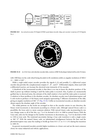
FIGURE 19.9  An optical encoder, US Digital LS7083 quadrature decoder chip, and counter (courtesy of US Digital,
                                 Inc.).


                                 FIGURE 19.10  An 8-bit Gray code absolute encoder disk, courtesy of BEI Technologies Industrial Encoder Division.


                                 with 1000 lines on the code wheel being decoded at 4X resolution yields an angular resolution of 360∞/
                                 (4 × 1000) = 0.09˚.
                                   While a single-ended output encoder provides the signals A, B, and possibly Z, a differential output
                                 encoder also provides the complementary outputs A′ , B′ , and Z′ . Differential outputs, when used with
                                 a differential receiver, can increase the electrical noise immunity of the encoder.
                                   A drawback of the incremental encoder is that there is no way to know the absolute position of the
                                 shaft at power-up without rotating it until the index pulse is received. Also, if pulses are momentarily
                                 garbled due to electrical noise, the estimate of the shaft rotation is lost until the index pulse is received.
                                 A solution to these problems is the absolute encoder. An absolute encoder uses k photointerrupters and
                                                                                      k
                                 k code tracks to produce a k-bit binary word uniquely representing 2  different orientations of the disk,
                                                               k
                                 giving an angular resolution of 360˚/2  (Fig. 19.10). Unlike an incremental encoder, an absolute encoder
                                 always reports the absolute angle of the encoder.
                                   The radial patterns on the tracks are arranged so that as the encoder rotates in one direction, the
                                 binary word increments or decrements according to a binary code. Although natural binary code is a
                                 possibility, the Gray code is a more common solution. With natural binary code, incrementing by one
                                 may change many or all of the bits, e.g., 7 to 8 in decimal is 0111 to 1000 in natural binary. With the
                                 Gray code, only one bit changes as the number increments or decrements, e.g., 7 to 8 in decimal is 0100
                                 to 1100 in Gray code. The rotational uncertainty during a Gray code transition is only a single count,
                                         k
                                 or 360˚/2 .  With the natural binary code, an infinitesimal misalignment between the lines and the
                                 photointerrupters may cause the reading to briefly go from 0111 (7) to 1111 (15) during the transition
                                 to 1000 (8).
                                   In general, incremental encoders provide higher resolution at a lower cost and are the most common
                                 choice for many industrial and robotic applications.


                                 ©2002 CRC Press LLC