
Page 387 - The Mechatronics Handbook
P. 387
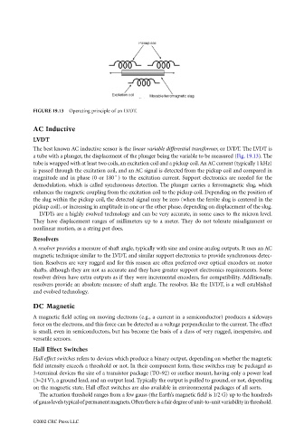
FIGURE 19.13  Operating principle of an LVDT.

                                 AC Inductive
                                 LVDT
                                 The best known AC inductive sensor is the linear variable differential transformer, or LVDT. The LVDT is
                                 a tube with a plunger, the displacement of the plunger being the variable to be measured (Fig. 19.13). The
                                 tube is wrapped with at least two coils, an excitation coil and a pickup coil. An AC current (typically 1 kHz)
                                 is passed through the excitation coil, and an AC signal is detected from the pickup coil and compared in
                                 magnitude and in phase (0 or 180˚) to the excitation current. Support electronics are needed for the
                                 demodulation, which is called synchronous detection. The plunger carries a ferromagnetic slug, which
                                 enhances the magnetic coupling from the excitation coil to the pickup coil. Depending on the position of
                                 the slug within the pickup coil, the detected signal may be zero (when the ferrite slug is centered in the
                                 pickup coil), or increasing in amplitude in one or the other phase, depending on displacement of the slug.
                                   LVDTs are a highly evolved technology and can be very accurate, in some cases to the micron level.
                                 They have displacement ranges of millimeters up to a meter. They do not tolerate misalignment or
                                 nonlinear motion, as a string pot does.
                                 Resolvers
                                 A resolver provides a measure of shaft angle, typically with sine and cosine analog outputs. It uses an AC
                                 magnetic technique similar to the LVDT, and similar support electronics to provide synchronous detec-
                                 tion. Resolvers are very rugged and for this reason are often preferred over optical encoders on motor
                                 shafts, although they are not as accurate and they have greater support electronics requirements. Some
                                 resolver drives have extra outputs as if they were incremental encoders, for compatibility. Additionally,
                                 resolvers provide an absolute measure of shaft angle. The resolver, like the LVDT, is a well established
                                 and evolved technology.

                                 DC Magnetic
                                 A magnetic field acting on moving electrons (e.g., a current in a semiconductor) produces a sideways
                                 force on the electrons, and this force can be detected as a voltage perpendicular to the current. The effect
                                 is small, even in semiconductors, but has become the basis of a class of very rugged, inexpensive, and
                                 versatile sensors.
                                 Hall Effect Switches
                                 Hall effect switches refers to devices which produce a binary output, depending on whether the magnetic
                                 field intensity exceeds a threshold or not. In their component form, these switches may be packaged as
                                 3-terminal devices the size of a transistor package (TO-92) or surface mount, having only a power lead
                                 (3–24 V), a ground lead, and an output lead. Typically the output is pulled to ground, or not, depending
                                 on the magnetic state. Hall effect switches are also available in environmental packages of all sorts.
                                   The actuation threshold ranges from a few gauss (the Earth’s magnetic field is 1/2 G) up to the hundreds
                                 of gauss levels typical of permanent magnets. Often there is a fair degree of unit-to-unit variability in threshold.


                                 ©2002 CRC Press LLC