
Page 383 - The Mechatronics Handbook
P. 383
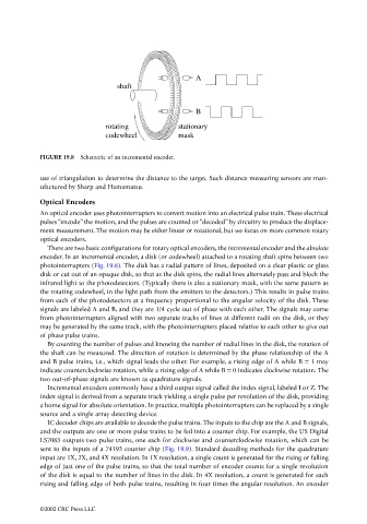
A
                                                       shaft


                                                                            B
                                                   rotating            stationary
                                                   codewheel           mask


                                 FIGURE 19.8  Schematic of an incremental encoder.

                                 use of triangulation to determine the distance to the target. Such distance measuring sensors are man-
                                 ufactured by Sharp and Hamamatsu.
                                 Optical Encoders
                                 An optical encoder uses photointerrupters to convert motion into an electrical pulse train. These electrical
                                 pulses “encode” the motion, and the pulses are counted or “decoded” by circuitry to produce the displace-
                                 ment measurement. The motion may be either linear or rotational, but we focus on more common rotary
                                 optical encoders.
                                   There are two basic configurations for rotary optical encoders, the incremental encoder and the absolute
                                 encoder. In an incremental encoder, a disk (or codewheel) attached to a rotating shaft spins between two
                                 photointerrupters (Fig. 19.8). The disk has a radial pattern of lines, deposited on a clear plastic or glass
                                 disk or cut out of an opaque disk, so that as the disk spins, the radial lines alternately pass and block the
                                 infrared light to the photodetectors. (Typically there is also a stationary mask, with the same pattern as
                                 the rotating codewheel, in the light path from the emitters to the detectors.) This results in pulse trains
                                 from each of the photodetectors at a frequency proportional to the angular velocity of the disk. These
                                 signals are labeled A and B, and they are 1/4 cycle out of phase with each other. The signals may come
                                 from photointerrupters aligned with two separate tracks of lines at different radii on the disk, or they
                                 may be generated by the same track, with the photointerrupters placed relative to each other to give out
                                 of phase pulse trains.
                                   By counting the number of pulses and knowing the number of radial lines in the disk, the rotation of
                                 the shaft can be measured. The direction of rotation is determined by the phase relationship of the A
                                 and B pulse trains, i.e., which signal leads the other. For example, a rising edge of A while B = 1 may
                                 indicate counterclockwise rotation, while a rising edge of A while B = 0 indicates clockwise rotation. The
                                 two out-of-phase signals are known as quadrature signals.
                                   Incremental encoders commonly have a third output signal called the index signal, labeled I or Z. The
                                 index signal is derived from a separate track yielding a single pulse per revolution of the disk, providing
                                 a home signal for absolute orientation. In practice, multiple photointerrupters can be replaced by a single
                                 source and a single array detecting device.
                                   IC decoder chips are available to decode the pulse trains. The inputs to the chip are the A and B signals,
                                 and the outputs are one or more pulse trains to be fed into a counter chip. For example, the US Digital
                                 LS7083 outputs two pulse trains, one each for clockwise and counterclockwise rotation, which can be
                                 sent to the inputs of a 74193 counter chip (Fig. 19.9). Standard decoding methods for the quadrature
                                 input are 1X, 2X, and 4X resolution. In 1X resolution, a single count is generated for the rising or falling
                                 edge of just one of the pulse trains, so that the total number of encoder counts for a single revolution
                                 of the disk is equal to the number of lines in the disk. In 4X resolution, a count is generated for each
                                 rising and falling edge of both pulse trains, resulting in four times the angular resolution. An encoder


                                 ©2002 CRC Press LLC