
Page 47 - The Mechatronics Handbook
P. 47
Analog-to-Digital Converters
The ADC can basically be typed by two parameters: the analog input range and the digital output range. As
an example, consider an ADC that is converting a voltage level ranging 0–12 V into a single byte of 8 bits.
In this example, each binary count increment reflects an increase in analog voltage of 1/256 of the maximum
12 V. There is an unusual twist to this conversion, however. Since a zero value represents 0 V, and a 128 value
represents half of the maximum value, 6 V in this example, the maximum decimal value of 255 represents
255/256 of the maximum voltage value, or 11.953125 V. A table of the equivalent values is shown below:
Binary Decimal Voltage
0000 0000 0 0.0
0000 0001 1 0.00390625
1000 0000 128 6.0
1111 1111 255 11.953125
An ADC that is implemented in the Motorola HC12 microcontroller produces 10 bits. While not
fitting so nicely into a single byte of data, this 10-bit ADC does give additional resolution. Using an input
range from 0 to 5 V, the decimal resolution per least significant bit is 4.88 mV. If the ADC had 8 bits of
output, the resolution per bit would be 19.5 mV, a fourfold difference. Larger voltages, e.g., from 0 to
12 V, can be scaled with a voltage divider to fit the 0–5 V range. Smaller voltages can be amplified to
span the entire range. A process known as successive approximation (using the Successive Approximation
Register or SAR in the Motorola chip) is used to determine the correct digital value.
3.3 Output Signals of a Mechatronic System
Digital-to-Analog Converters
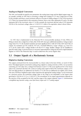
The output command from the microcontroller is a binary value in bit, byte (8 bits), or word (16 bits)
form. This digital signal is converted to analog using a digital-to-analog converter, or DAC. Let us examine
converting an 8-bit value into a voltage level between 0 and 12 V. The most significant bit in the binary
value to be converted (decimal 128) creates an analog value equal to half of the maximum output, or 6 V.
The next digit produces an additional one fourth, or 3 V, the next an additional one eighth, and so forth.
The sum of all these weighted output values represents the appropriate analog voltage. As was mentioned
in a previous section, the maximum voltage value in the range is not obtainable, as the largest value
generated is 255/256 of 12 V, or 11.953125 V. The smoothness of the signal representation depends on
the number of bits accepted by the DAC and the range of the output required. Figure 3.7 demonstrates
a simplified step function using a one-byte binary input and 12-V analog output.
Voltage Level Output ( 0 - 12 volts )
8 bit Value Input ( 0-255 decimal )
FIGURE 3.7 DAC stepped output.
©2002 CRC Press LLC