
Page 44 - The Mechatronics Handbook
P. 44
The Mechatronic System
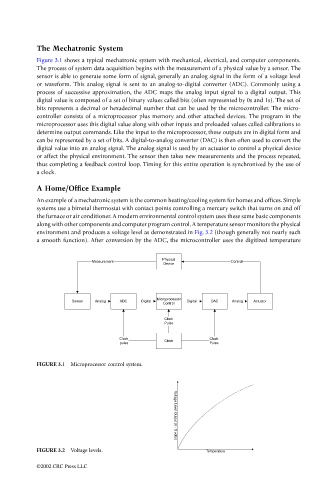
Figure 3.1 shows a typical mechatronic system with mechanical, electrical, and computer components.
The process of system data acquisition begins with the measurement of a physical value by a sensor. The
sensor is able to generate some form of signal, generally an analog signal in the form of a voltage level
or waveform. This analog signal is sent to an analog-to-digital converter (ADC). Commonly using a
process of successive approximation, the ADC maps the analog input signal to a digital output. This
digital value is composed of a set of binary values called bits (often represented by 0s and 1s). The set of
bits represents a decimal or hexadecimal number that can be used by the microcontroller. The micro-
controller consists of a microprocessor plus memory and other attached devices. The program in the
microprocessor uses this digital value along with other inputs and preloaded values called calibrations to
determine output commands. Like the input to the microprocessor, these outputs are in digital form and
can be represented by a set of bits. A digital-to-analog converter (DAC) is then often used to convert the
digital value into an analog signal. The analog signal is used by an actuator to control a physical device
or affect the physical environment. The sensor then takes new measurements and the process repeated,
thus completing a feedback control loop. Timing for this entire operation is synchronized by the use of
a clock.
A Home/Office Example
An example of a mechatronic system is the common heating/cooling system for homes and offices. Simple
systems use a bimetal thermostat with contact points controlling a mercury switch that turns on and off
the furnace or air conditioner. A modern environmental control system uses these same basic components
along with other components and computer program control. A temperature sensor monitors the physical
environment and produces a voltage level as demonstrated in Fig. 3.2 (though generally not nearly such
a smooth function). After conversion by the ADC, the microcontroller uses the digitized temperature
Physical
Measurement Control
Device
Microprocessor
Sensor Analog ADC Digital Digital DAC Analog Actuator
Control
Clock
Pulse
Clock Clock Clock
pulse Pulse
FIGURE 3.1 Microprocessor control system.
Voltage Level Output (0 - 5 volts)
FIGURE 3.2 Voltage levels. Temperature
©2002 CRC Press LLC