Page 146 - Thomson, William Tyrrell-Theory of Vibration with Applications-Taylor _ Francis (2010)
P. 146

Sec. 5.1   The Normal Mode Analysis                            133


                                           a;? = 0 .6 3 4 ^


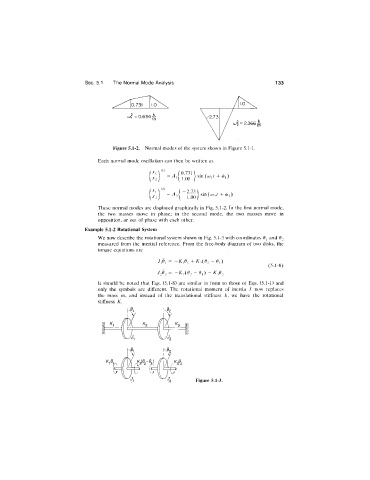
                                       Figure 5.1-2.  Normal modes of the system shown in Figure 5.1-1.

                                  Each  normal  mode  oscillation  can  then  be written  as
                                                      ( 1)
                                                        _  .  .  0.731  . . .    ,  ,  ,  X

                                                        —^ i\  1  1.00  } sin (w,/  +  (//,)
                                                        - A ,  -2.73  sin   +  ^ 2)
                                                               1.00
                                  These normal  modes are displayed graphically in  Fig. 5.1-2.  In the first normal  mode,
                                  the  two  masses  move  in  phase;  in  the  second  mode,  the  two  masses  move  in
                                  opposition,  or out of phase with  each  other.
                             Example 5.1-2  Rotational  System
                                  We now describe the rotational system shown in  Fig. 5.1-3 with coordinates  0^ and  62

                                  measured  from  the  inertial  reference.  From  the  free-body  diagram  of two  disks,  the
                                  torque  equations  are
                                                     7,0,  =  -K,e,  + K2{02 -   0,)
                                                                                          (5.1-8)
                                                     7202 =  - ^ 2(^2 -  ^1)  -  ^ 3^2
                                  It  should  be  noted  that  Eqs.  (5.1-8)  are  similar  in  form  to  those  of  Eqs.  (5.1-1)  and
                                  only  the  symbols  are  different.  The  rotational  moment  of  inertia  7  now  replaces
                                  the  mass  m,  and  instead  of  the  translational  stiffness  /c,  we  have  the  rotational
                                  stiffness  K.


                                                                  Figure 5.1-3.
   141   142   143   144   145   146   147   148   149   150   151