Page 186 - Thomson, William Tyrrell-Theory of Vibration with Applications-Taylor _ Francis (2010)
P. 186

Sec. 6.1   Flexibility Influence Coefficients                  173


                                      The complete  flexibility matrix is  now the  sum of the  three prior  matrices:
                                              (       1      1          1       (  \
                                                                                 /,
                                                      1    1   1      1   1

                                                 ^=                             <
                                                                          ^2
                                                      1    1   1    1   1    1
                                                               k l      ^2 ^  ^3  V ;

                                  Note  the symmetry of the  matrix about  the  diagonal.
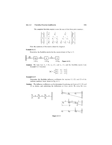
                              Example 6.1-2
                                  Determine  the  flexibility matrix for the system shown  in  Fig.  6.1-2.


                                                                     Figure 6.1-2.
                                                               and  ^3  =  k,  and  the  flexibility  matrix  from
                                  Example 6.1-1  becomes
                                                              0.5  0.5  0.5'
                                                              0.5  1.5  1.5
                                                              0.5  1.5  2.5
                              Example 6.1-3
                                  Determine  the  flexibility  influence  coefficients  for  stations  (1),  (2),  and  (3)  of  the
                                  uniform cantilever beam  shown  in  Fig. 6.1-3.
                              Solution:  The influence coefficients can be determined by placing unit loads at (1), (2), and
                                  (3)  as  shown,  and  calculating  the  deflections  at  these  points.  By  using  the  area


                                       7    ni2  ^3
                                                 - o
                                   (1)    (2)     (3)


                                                                    <^I3   i^23    i^33

                                                          Figure 6.1-3.
   181   182   183   184   185   186   187   188   189   190   191