
Page 191 - Thomson, William Tyrrell-Theory of Vibration with Applications-Taylor _ Francis (2010)
P. 191
178 Properties of Vibrating Systems Chap. 6
’43 ''44
'
e
yy/7777/7:^/.
( a )
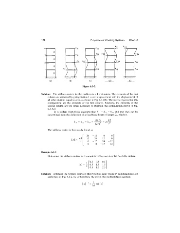
Figure 6.3-2.
Solution: The stiffness matrix for the problem is a 4 X 4 matrix. The elements of the first
eolumn are obtained by giving station 1 a unit displacement with the displacement of
all other stations equal to zero, as shown in Fig. 6.3-2(b). The forces required for this
configuration are the elements of the first column. Similarly, the elements of the
second column are the forces necessary to maintain the configuration shown in Fig.
6.3-2(c).
It is evident from these diagrams that k22 = ^33 arid that they can be
determined from the deflection of a fixed-fixed beam of length 2/, which is
k \\ — — ^33 “ ^^,^3 “ 24
(2/)’
The stiffness matrix is then easily found as
24 -1 2 0 0
El -1 2 24 -1 2 0
0 -1 2 24 -1 2
0 0 -1 2 12
Example 6.3-3
Determine the stiffness matrix for Example 6.1-2 by inverting the flexibility matrix:
0.5 0.5 0.5
[«] = T 0.5 1.5 1.5
0.5 1.5 2.5
Solution: Although the stiffness matrix of this system is easily found by summing forces on
each mass in Fig. 6.1-2, we demonstrate the use of the mathematical equation
adj [a]