
Page 194 - Thomson, William Tyrrell-Theory of Vibration with Applications-Taylor _ Francis (2010)
P. 194
Sec. 6.4 Stiffness Matrix of Beam Elements 181
Also presented here are force and moment relationships for a pinned beam.
Although the pinned beam does not conform to the usual definition of beam
stiffness, its force and moment relationships are often convenient, and are pre
sented here as Figure 6.4-2(a).
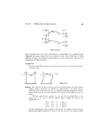
Example 6.4-1
Determine the stiffness matrix for the square frame of Fig. 6.4-3. Assume the corners
to remain at 90°.
Figure 6.4-3.
Solution: The method to be illustrated here provides an introduction to the finite element
method, which is discussed later. Briefly, the displacements at the joints (corners
joining the three beam elements) must be compatible. Ensuring equilibrium of forces
at the corners from the free-body diagrams, the elements of the stiffness matrix are
found.
With the applied forces equal to F,, Mj, and A/^, the displacement of the
corners are rq, and 6 2 , and the stiffness matrix relating the force to the
displacement is
^ 11 ^.2 k j3
^ 4
M, = ^21 ^22
M2) _^31 ^32 ^ 2 2 r
For the determination of the elements of this matrix, the frame is shown with each
displacement applied separately in Fig. 6.4-4. The first column of the stiffness matrix