Page 461 - Thomson, William Tyrrell-Theory of Vibration with Applications-Taylor _ Francis (2010)
P. 461
448                                      Random Vibrations   Chap. 13
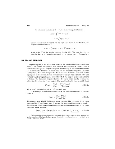
                                      For  a  harmonic excitation  fit)  =   the  preceding equation beeomes

                                                       x(t)  =  r e ‘^^'~^^h(r) dr
                                                            A)
                                                           =   rh{T)e    dr
                                                               f)
                                  Beeause  the  steady-state  output  for  the  input  yit) = e""'  is  x  =  H{co)e‘'^',  the
                                  frequeney-response  function  is

                                                H{w)=  rh{T)e  ‘^^^ dr =  r   h{r)e  •^'^^dr
                                                       f)            J-yc
                                  which  is  the  FT  of  the  impulse  response  funetion  hit).  The  lower  limit  in  the
                                  preeeding  integral  has  been  ehanged  from  0  to  -^c  because  hit) =  0  for  negative  t.


                       13.8  FTs AND RESPONSE
                              In  engineering  design,  we  often  need  to  know  the  relationship  between  different
                              points  in  the  system.  For  example,  how  much  of the  roughness  of a  typical  road  is
                              transmitted  through  the  suspension  system  to  the  body  of  an  automobile?  (Here
                              the  term  transfer  function^  is  often  used  for  the  frequency-response  function.)
                              Furthermore,  it  is  often  not  possible  to  introduce  a  harmonic  excitation  to  the
                              input  point  of  the  system.  It  may  be  necessary  to  accept  measurements  xit)  and
                              y (0  at two different points  in  the system for which the frequency response function
                              is  desired.  The  frequency  response  function  for  these  points  can  be  obtained  by
                              taking  the  FT  of the  input  and  output.  The  quantity  Hico)  is  then  available  from
                                                         y{(o)   FT of output
                                                 H{co)  =                                (13.8-1)
                                                         X{oj)    FT of input
                              where  X{co)  and  Vico)  are  the  FT of  xit)  and  yit).
                                  If we  multiply  and  divide  this  equation  by  the  complex conjugate  A^*(o)),  the
                              result  is
                                                             Y{co)X^{co)
                                                     H(co)                               (13.8-2)
                                                             X(co)X^(co)
                              The  denominator  X{co)X"'{o))  is  now  a  real  quantity.  The  numerator  is  the  cross
                              spectrum  Y(oj)X*ico) between  the  input and the output  and  is  a complex quantity.
                              The  phase  of  Hico)  is  then  found  from  the  real  and  imaginary  parts  of the  cross
                              spectrum,  which  is  simply
                                                               =\Y{oj)X*(co)\/4>y  -   4>,   (13.8-3)

                                  ^Strictly speaking,  the  transfer function  is the  ratio of the  Laplace  transform of the output  to the
                              Laplace  transform  of the  input.  In  the  frequency  domain,  however,  the  real  part  of  s = a + ico  is  zero,
                              and  the  LT becomes  the  FT.

