
Page 92 - Thomson, William Tyrrell-Theory of Vibration with Applications-Taylor _ Francis (2010)
P. 92
Sec. 3.13 Vibration-Measuring Instruments 79
Figure 3.11-1.
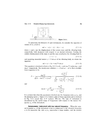
To determine the behavior of such instruments, we consider the equation of
motion of m, which is
mx = - c ( i - y) - k{x - y) (3.11-1)
where x and y are the displacement of the seismic mass and the vibrating body,
respectively, both measured with respect to an inertial reference. Letting the
relative displacement of the mass m and the case attached to the vibrating body be
z - y (3.11-2)
and assuming sinusoidal motion y = T sin wr of the vibrating body, we obtain the
equation
mz + cz + kz = mcú^Y sin cot (3.11-3)
This equation is identical in form to Eq. (3.2-1) with z and moj^Y replacing x and
meco^, respectively. The steady-state solution z = Z sin(ior —0) is then available
from inspection to be
y (
Z - , - . , . (3^11-4)
mo)^) + {c(o)
1 + 2^
0).
and
(x)C
tan (/) = (3.11-5)
k - mcx)^
1
It is evident then that the parameters involved are the frequency ratio (o/co^ and
the damping factor Figure 3.11-2 shows a plot of these equations and is identical
to Fig. 3.3-2 except that Z /Y replaces MX/me. The type of instrument is
determined by the useful range of frequencies with respect to the natural fre
quency 0)^ of the instrument.
Seismometer: instrument with low natural frequency. When the natu
ral frequency of the instrument is low in comparison to the vibration frequency
(X) to be measured, the ratio (o/co^ approaches a large number, and the relative