
Page 96 - Thomson, William Tyrrell-Theory of Vibration with Applications-Taylor _ Francis (2010)
P. 96
Sec. 3.13 Vibration-Measuring Instruments 83
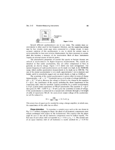
Piezoelectric
crystal
Figure 3.11-6.
Several different aecelerometers are in use today. The seismic mass ac
celerometer is often used for low-frequency vibration, and the supporting springs
may be four electric strain gage wires connected in a bridge circuit. A more
accurate variation of this accelerometer is one in which the seismic mass is
servo-controlled to have zero relative displacement; the force necessary to accom
plish this becomes a measure of the acceleration. Both of these instruments
require an external source of electric power.
The piezoelectric properties of crystals like quartz or barium titanate are
utilized in accelerometers for higher-frequency measurements. The crystals are
mounted so that under acceleration, they are either compressed or bent to
generate an electric charge. Figure 3.11-6 shows one such arrangement. The
natural frequency of such accelerometers can be made very high, in the 50,000-Hz
range, which enables acceleration measurements to be made up to 3000 Hz. The
size of the crystal accelerometer is very small, approximately 1 cm in diameter and
height, and it is remarkably rugged and can stand shocks as high as 10,000 g’s.
The sensitivity of the crystal accelerometer is given either in terms of charge
(picocoulombs = pC = 10“ ^^ Coulombs) per g, or in terms of voltage (millivolts =
mV = 10“'^ V) per g. Because the voltage is related to the charge by the equation
E = Q/C, the capacitance of the crystal, including the shunt capacitance of the
connecting cable, must be specified. Typical sensitivity for a crystal accelerometer
is 25 pC/g with crystal capacitance of 500 pF (picofarads). The equation E = Q/ C
then gives 25/500 = 0.050 V/g = 50 mV/g for the sensitivity in terms of voltage.
If the accelerometer is connected to a vacuum-tube voltmeter through a 3-m length
of cable of capacitance 300 pF, the open-circuit output voltage of the accelerome
ter will be reduced to
500
50 X 31.3 mV/g
500 + 300
This severe loss of signal can be avoided by using a charge amplifier, in which case,
the capacitance of the cable has no effect.
Phase distortion. To reproduce a complex wave such as the one shown in
Fig. 3.11-7 without changing its shape, the phase of all harmonic components must
remain unchanged with respect to the fundamental. This requires that the phase
angle be zero or that all the harmonic components must be shifted equally. The
first case of zero phase shift corresponds to = 0 for co/cj^ < 1. The second case
of an equal timewise shift of all harmonics is nearly satisfied for = 0.70 for