
Page 102 - Thermal Hydraulics Aspects of Liquid Metal Cooled Nuclear Reactors
P. 102
76 Thermal Hydraulics Aspects of Liquid Metal Cooled Nuclear Reactors
each). The free surface of the water model is at atmospheric pressure. The facility is
designated for a nominal water flow rate of 5.6 L/s. The maximum ΔT during the tests
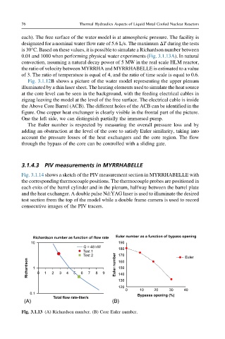
is 30°C. Based on these values, it is possible to simulate a Richardson number between
0.01 and 1000 when performing physical water experiments (Fig. 3.1.13A). In natural
convection, assuming a natural decay power of 5 MW in the real scale HLM reactor,
the ratio of velocity between MYRRHA and MYRRHABELLE is estimated to a value
of 3. The ratio of temperature is equal of 4, and the ratio of time scale is equal to 0.6.
Fig. 3.1.12B shows a picture of the water model representing the upper plenum
illuminated by a thin laser sheet. The heating elements used to simulate the heat source
at the core level can be seen in the background, with the feeding electrical cables in
zigzag leaving the model at the level of the free surface. The electrical cable is inside
the Above Core Barrel (ACB). The different holes of the ACB can be identified in the
figure. One copper heat exchanger is clearly visible in the frontal part of the picture.
One the left side, we can distinguish partially the immersed pump.
The Euler number is respected by measuring the overall pressure loss and by
adding an obstruction at the level of the core to satisfy Euler similarity, taking into
account the pressure losses of the heat exchangers and the core region. The flow
through the bypass of the core can be controlled with a sliding gate.
3.1.4.3 PIV measurements in MYRRHABELLE
Fig. 3.1.14 shows a sketch of the PIV measurement section in MYRRHABELLE with
the corresponding thermocouple positions. The thermocouple probes are positioned in
each exits of the barrel cylinder and in the plenum, halfway between the barrel plate
and the heat exchanger. A double pulse Nd:YAG laser is used to illuminate the desired
test section from the top of the model while a double frame camera is used to record
consecutive images of the PIV tracers.
Richardson number as function of flow rate Euler number as a function of bypass opening
10 190
Q = 48 kW
180
Test 1
Test 2 170 Euler
Richardson 1 0 1 2 3 4 5 6 7 8 9 Euler number 160
150
140
130
120
0 10 20 30 40
0.1 Bypasss opening (%)
Total flow rate-liter/s
(A) (B)
Fig. 3.1.13 (A) Richardson number. (B) Core Euler number.