
Page 103 - Thermal Hydraulics Aspects of Liquid Metal Cooled Nuclear Reactors
P. 103
Rod bundle and pool-type experiments in water serving liquid metal reactors 77
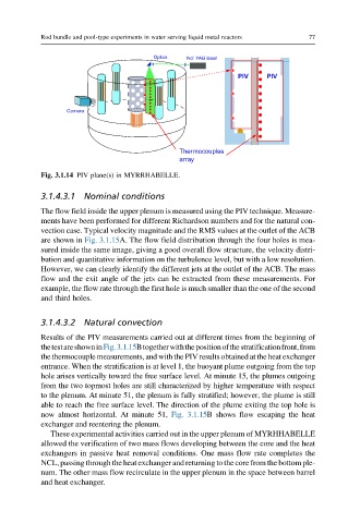
Optics Nd: YAG laser
PIV PIV
Camera
Thermocouples
array
Fig. 3.1.14 PIV plane(s) in MYRRHABELLE.
3.1.4.3.1 Nominal conditions
The flow field inside the upper plenum is measured using the PIV technique. Measure-
ments have been performed for different Richardson numbers and for the natural con-
vection case. Typical velocity magnitude and the RMS values at the outlet of the ACB
are shown in Fig. 3.1.15A. The flow field distribution through the four holes is mea-
sured inside the same image, giving a good overall flow structure, the velocity distri-
bution and quantitative information on the turbulence level, but with a low resolution.
However, we can clearly identify the different jets at the outlet of the ACB. The mass
flow and the exit angle of the jets can be extracted from these measurements. For
example, the flow rate through the first hole is much smaller than the one of the second
and third holes.
3.1.4.3.2 Natural convection
Results of the PIV measurements carried out at different times from the beginning of
thetestareshowninFig.3.1.15Btogetherwiththepositionofthestratificationfront,from
the thermocouple measurements, and with the PIV results obtained at the heat exchanger
entrance. When the stratification is at level 1, the buoyant plume outgoing from the top
hole arises vertically toward the free surface level. At minute 15, the plumes outgoing
from the two topmost holes are still characterized by higher temperature with respect
to the plenum. At minute 51, the plenum is fully stratified; however, the plume is still
able to reach the free surface level. The direction of the plume exiting the top hole is
now almost horizontal. At minute 51, Fig. 3.1.15B shows flow escaping the heat
exchanger and reentering the plenum.
These experimental activities carried out in the upper plenum of MYRHHABELLE
allowed the verification of two mass flows developing between the core and the heat
exchangers in passive heat removal conditions. One mass flow rate completes the
NCL, passing through the heat exchanger and returning to the core from the bottom ple-
num. The other mass flow recirculate in the upper plenum in the space between barrel
and heat exchanger.