
Page 88 - Thermal Hydraulics Aspects of Liquid Metal Cooled Nuclear Reactors
P. 88
Rod bundle and pool-type experiments in water serving liquid metal reactors 63
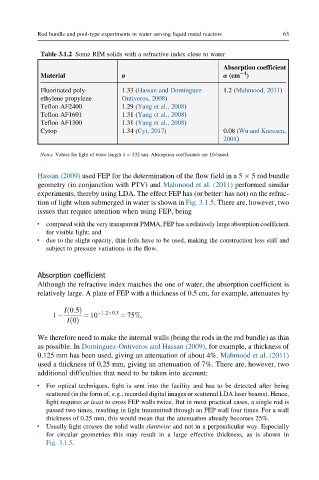
Table 3.1.2 Some RIM solids with a refractive index close to water
Absorption coefficient
n 21
Material α (cm )
Fluorinated poly- 1.33 (Hassan and Dominguez- 1.2 (Mahmood, 2011)
ethylene propylene Ontiveros, 2008)
Teflon AF2400 1.29 (Yang et al., 2008)
Teflon AF1601 1.31 (Yang et al., 2008)
Teflon AF1300 1.31 (Yang et al., 2008)
Cytop 1.34 (Cyt, 2017) 0.08 (Wu and Knoesen,
2001)
Notes: Values for light of wave length λ ¼ 532 nm. Absorption coefficients are 10-based.
Hassan (2009) used FEP for the determination of the flow field in a 5 5 rod bundle
geometry (in conjunction with PTV) and Mahmood et al. (2011) performed similar
experiments, thereby using LDA. The effect FEP has (or better: has not) on the refrac-
tion of light when submerged in water is shown in Fig. 3.1.5. There are, however, two
issues that require attention when using FEP, being
l compared with the very transparent PMMA, FEP has a relatively large absorption coefficient
for visible light; and
l due to the slight opacity, thin foils have to be used, making the construction less stiff and
subject to pressure variations in the flow.
Absorption coefficient
Although the refractive index matches the one of water, the absorption coefficient is
relatively large. A plate of FEP with a thickness of 0.5 cm, for example, attenuates by
Ið0:5Þ 1:2 0:5
1 ¼ 10 ¼ 75%:
Ið0Þ
We therefore need to make the internal walls (being the rods in the rod bundle) as thin
as possible. In Dominguez-Ontiveros and Hassan (2009), for example, a thickness of
0.125 mm has been used, giving an attenuation of about 4%. Mahmood et al. (2011)
used a thickness of 0.25 mm, giving an attenuation of 7%. There are, however, two
additional difficulties that need to be taken into account:
For optical techniques, light is sent into the facility and has to be detected after being
l
scattered (in the form of, e.g., recorded digital images or scattered LDA laser beams). Hence,
light requires at least to cross FEP walls twice. But in most practical cases, a single rod is
passed two times, resulting in light transmitted through an FEP wall four times. For a wall
thickness of 0.25 mm, this would mean that the attenuation already becomes 25%.
l Usually light crosses the solid walls slantwise and not in a perpendicular way. Especially
for circular geometries this may result in a large effective thickness, as is shown in
Fig. 3.1.5.