
Page 260 - Trenchless Technology Piping Installation and Inspection
P. 260
224 Cha pte r F i v e
5.5.3 Applications
Pull Force
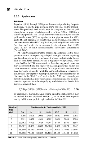
Equations (5.18) through (5.21) provide means of predicting the peak
pull force, T , on the pipe during a Mini- (or Midi-) HDD installa-
1
D
tions. The predicted load should then be compared to the safe pull
strength for the pipe, which is provided in Table 5.2 for HDPE for a
variety of pipe sizes. The safe pull strength (lb) is based upon the safe
pull tensile stress (SPS), as applied to the pipe cross-section (PPI,
2008). The SPS accounts for the effective load duration, assumed to be
one hour for the Mini-HDD applications, and a significant reduction
(less than half) relative to the nominal tensile test strength of HDPE
2
(3200 lb/in. ) to limit nonrecoverable viscoelastic deformation
(Petroff, 2006).
ASTM F1962 requires that the predicted peak tensile load to be no
greater than the corresponding safe pull strength, without requiring
additional margin or the employment of any explicit safety factor.
This is considered reasonable for a typically well-planned, well-
controlled Maxi-HDD operation since there is a degree of conserva-
tism incorporated into the employed material properties, and in the
other parametric values. However, for a typical Mini-HDD installa-
tion, there may be a wide variability in the as-built route characteris-
tics, such as the degree of actual path curvature and undulations, as
discussed in the “Pull Force” section in Sec. 5.5.2, and other depar-
tures from the idealizations with various approximations and assump-
tions incorporated into the simplifying model described herein. It is
therefore required that:
T [Eqs. (5.18) to (5.22)] <safe pull strength (Table 5.2) (5.24)
1
D
by a reasonable margin (e.g., depending upon the application), it may
1
be desired that the predicted tension T be no more than approxi-
D
mately half the safe pull strength indicated in Table 5.2.
Nominal Pipe Diameter to Thickness Ratio (DR)
Size
(in.) 7.3 9 11 13.5 15.5 17 21
2 2998 2505 2096 1739 1530 1404 1085
3 6511 5439 4551 3777 3324 3049 2356
4 10,762 8991 7524 6244 5494 5040 3895
6 23,327 19,488 16,307 13,533 11,909 10,924 8442
8 38,399 32,080 26,844 22,278 19,603 17,982 13,897
12 86,398 72,180 60,398 50,125 44,108 40,461 31,268
TABLE 5.2 Safe Pull Strength (lb), HDPE Pipe, 12 Hours