
Page 395 - Trenchless Technology Piping Installation and Inspection
P. 395
Inspection and QA/QC for Trenchless Installation and Replacement Methods 345
5. Pipe must be without any significant dimensional or surface
deformities. All pipes must be free of visible cracks, holes,
foreign material, foreign inclusions, blisters, or other deleteri-
ous or injurious faults or defects. Any section of the pipe with
a gash, blister, abrasion, nick, scar, or other deleterious fault
greater in depth than 10 percent of the wall thickness, must
not be used and must be immediately removed from the
site.
6. Any of the following defects warrants pipe rejection:
• Concentrated ridges, discoloration, excessive spot rough-
ness, and pitting
• Insufficient or variable wall thickness
• Pipe damage from bending, crushing, stretching, or other
stress
• Pipe damage that impacts the pipe strength, the intended
use, the internal diameter of the pipe, and internal rough-
ness characteristics
• Any other defect of manufacturing or handling
Protective Coatings (Steel Pipe)
The product pipe may be exposed to significant abrasion during pull-
back. Therefore, a coating to provide a corrosion barrier as well as an
abrasion barrier is required. The coating must be bonded well to the
pipe and have a hard smooth surface to resist soil stresses and reduce
friction. Usually a mill-applied fusion bonded epoxy (FBE) coating is
required for steel pipes.
8.6.3 Construction
Minimum Allowable Depths
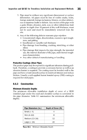
The minimum allowable installation depth of cover of a HDD
installed pipe under the road and shoulder surface is correlated to
the pipe diameter. Table 8.1 summarizes the minimum allowable
depths.
Pipe Diameters (in.) Depth of Cover (ft)
Small (< 4) 4
Mini (4–12) 8
Medium (13–24) 12
Large (> 24) 16
TABLE 8.1 Minimum Allowable Depth