
Page 407 - Trenchless Technology Piping Installation and Inspection
P. 407
Inspection and QA/QC for Trenchless Installation and Replacement Methods 357
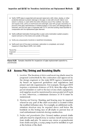
Verify HDPE pipe is supported and secured reasonably with rollers, skates, or other
protective devices to prevent damage to the pipe, is new with smooth interior and
exterior surfaces, is used within the entire influence area of the roadbed, has clean
and square ends, joints are butt-fused and watertight, pipe with gouges exceeding 10
percent of the pipe wall thickness or kinked sections is not used, and damaged pipe is
removed, and the host pipe is inspected with CCTV, and the bursting head diameter is
comparable with the replacement pipe diameter.
Verify sufficient lubrication fluid quantity is used, and a lubrication system properly
injects lubricant on the inside and outside of the pipe.
Verify any unsuccessful borehole is backfilled immediately.
Verify each end of the pipe is enclosed, restoration is completed, and attach
Inspector’s Daily Report (IDR), form 2228.
Permit No. __________________________
Inspector: ___________________________
Date: _______________________________
FIGURE 8.25 Sample checklist for inspection of pipe-replacement operations.
(Continued)
8.8 Access Pits/Driving and Receiving Shafts
1. Location: The location of drive and receiving shafts must be
proposed (submitted) by the contractors and approved by
the design engineer or the state DOT/agency/municipal-
ity based on approved guidelines and regulations and
project and site requirements. For example, Michigan DOT
requires a minimum distance of 20 ft, from the edge of the
paved shoulder or curb to the face of any shaft, equipment,
and supplies must be maintained in areas posted at 45 mph
or less; otherwise, a minimum distance of 30 ft must be
maintained.
2. Sheeting and bracing: Sheeting and bracing may be required
whenever any part of the shaft excavation is located within
the roadbed influence area. For example, an additional earth-
retention structure may be required above and below the
borehole on the boring face of all shafts to prevent loss of
road embankment materials during construction.
3. Surface and groundwater flow: Ground surface around shafts
and pits must be sloped away so surface runoff moves away
from shafts and pits. To remove any storm or groundwater
from shafts and pits, a sump pump must be installed at a pit
at the bottom of the shaft.