
Page 193 - Tribology in Machine Design
P. 193
178 Tribology in machine design
equation. Equation (5.7) transformed into the cylindrical coordinates is
where the velocities of the two surfaces are R l and R 2 in the radial direction,
T! and T 2 in the tangential direction, and V l and V 2 in the axial direction
across the film. For most bearings many of the terms may be dropped, and
particularly those which imply a stretching of the surfaces.
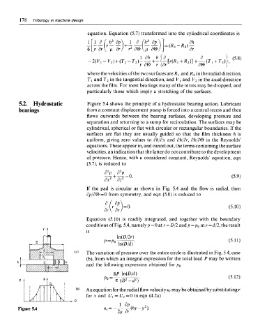
5.2. Hydrostatic Figure 5.4 shows the principle of a hydrostatic bearing action. Lubricant
bearings from a constant displacement pump is forced into a central recess and then
flows outwards between the bearing surfaces, developing pressure and
separation and returning to a sump for recirculation. The surfaces may be
cylindrical, spherical or flat with circular or rectangular boundaries. If the
surfaces are flat they are usually guided so that the film thickness h is
uniform, giving zero values to dh/dx and dh/dr, dh/d& in the Reynolds'
equations. These appear in, and cancel out, the terms containing the surface
velocities, an indication that the latter do not contribute to the development
of pressure. Hence, with u considered constant, Reynolds' equation, eqn
(5.7), is reduced to
If the pad is circular as shown in Fig. 5.4 and the flow is radial, then
dp/d&=0 from symmetry, and eqn (5.8) is reduced to
Equation (5.10) is readily integrated, and together with the boundary
conditions of Fig. 5.4, namely p = 0 at r — D/2 and p = p 0 at r = d/2, the result
ic
The variation of pressure over the entire circle is illustrated in Fig. 5.4, case
(b), from which an integral expression for the total load P may be written
and the following expression obtained for p 0
An equation for the radial flow velocity u r may be obtained by substituting r
for x and 17 1 = U 2 =0 in eqn (4.2a)
Figure 5.4