
Page 191 - Tribology in Machine Design
P. 191
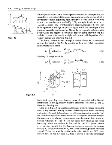
176  Tribology in machine design

                                 Each equation shows that a velocity profile consists of a linear portion, the
                                 second term to the right of the equals sign, and a parabolic portion which is
                                 subtracted or added depending upon the sign of the first term. For velocity
                                 u the second term is represented in Fig. 5.2 by a straight line drawn between
                                                      2
                                 l/i and U 2. Since — (hy—y )/2fj, is always negative, the sign of the first term
                                 is the opposite of the sign of dp/dx or dp/dz, which are the slopes of the
                                 pressure versus the position curves. Notice the correspondence between the
                                 positive, zero and negative slopes of the pressure curve, shown in Fig. 5.2,
                                 and the concave (subtracted), straight and convex (added) profiles of the
     Figure 5.2                  velocity curves also shown in Fig. 5.2.
                                   The flow q x normal to and through a section of area h dz is estimated
                                 next, as illustrated in Fig. 5.3. By substitution for u eqn (5.2a), integration
                                 and application of limits


                                 Similarly, through area h dx
                                            » L.


                      Figure 5.3

                                 Note that these flows are through areas of elemental width. Second
                                 integrations \q x and \q z must be made to obtain the total flows Q x and Q z
                                 through a bearing slot.
                                   Case (a) in Fig. 5.3 represents an elemental geometric space within the
                                 fluid, at any instant extending between the bearing surfaces but remaining
                                 motionless. Through its boundaries oil is flowing. A positive velocity V t of
                                 the lower bearing surface pushes oil inwards through the lower boundary of
                                 the space and gives a flow q v in the same sense as the inward flows q x and q z.
                                 Surface velocities L^ and Wi do not cause flow through the lower
                                 boundary, since the surface is flat and in the X-Z plane. Hence
                                 q i = V ldxdz. Because the top bearing surface is inclined, its positive
                                 velocity V 2 causes outward flow V 2 dx dz. Furthermore, positive velocities
                                 1/2 and W 2 together with the positive surface slopes dh/dx and dh/dz cause
                                 inward flow. In Fig. 5.3, case (a), there is shown a velocity component