
Page 205 - Tribology in Machine Design
P. 205
190 Tribology in machine design
increasingly eccentric position, thus forming a wedge-shaped oil film where
load-supporting pressure is generated. The eccentricity e is measured from
Vflv >
/ / v ° \, the bearing centre O b to the shaft centre Oj, as shown in Fig. 5.12. The
r [
maximum possible eccentricity equals the radial clearance c, or half the
/ L - ,/V->\. i initial difference in diameters, c d, and it is of the order of one-thousandth of
0
Vr^ ' )/ the diameter. It will be convenient to use an eccentricity ratio, defined as
\ \ecos9 j |\ / /
£=e/c. Then e =0 at no load, and e has a maximum value of 1.0 if the shaft
should touch the bearing under extremely large loads.
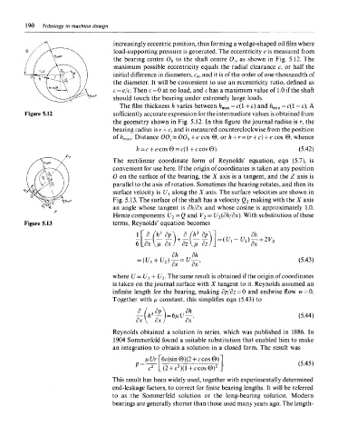
The film thickness h varies between /i max = c(l + e) and h min — c(l — e). A
Figure 5.12 sufficiently accurate expression for the intermediate values is obtained from
the geometry shown in Fig. 5.12. In this figure the journal radius is r, the
bearing radius is r + c, and is measured counterclockwise from the position
of h max. Distance 00j K 00 b + e cos 0, or h + r — (r + c) + e cos 0, whence
The rectilinear coordinate form of Reynolds' equation, eqn (5.7), is
convenient for use here. If the origin of coordinates is taken at any position
0 on the surface of the bearing, the X axis is a tangent, and the Z axis is
parallel to the axis of rotation. Sometimes the bearing rotates, and then its
surface velocity is Ui along the X axis. The surface velocities are shown in
Fig. 5.13. The surface of the shaft has a velocity Q 2 making with the X axis
an angle whose tangent is dh/dx and whose cosine is approximately 1.0.
Hence components U 2=Q and V 2 = U 2(dh/dx). With substitution of these
Figure 5.13 terms, Reynolds' equation becomes
where U= t/ t + U 2. The same result is obtained if the origin of coordinates
is taken on the journal surface with X tangent to it. Reynolds assumed an
infinite length for the bearing, making 8p/dz=Q and endwise flow w=0.
Together with JJL constant, this simplifies eqn (5.43) to
Reynolds obtained a solution in series, which was published in 1886. In
1904 Sommerfeld found a suitable substitution that enabled him to make
an integration to obtain a solution in a closed form. The result was
This result has been widely used, together with experimentally determined
end-leakage factors, to correct for finite bearing lengths. It will be referred
to as the Sommerfeld solution or the long-bearing solution. Modern
bearings are generally shorter than those used many years ago. The length-