
Page 208 - Tribology in Machine Design
P. 208
Sliding-element bearings 193
and
wheno
and
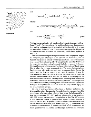
Figure 5.15
With an increasing load, e will vary from 0 to 1.0, and the angle </> will vary
from 90° to 0°. Correspondingly, the position of minimum film thickness,
Jz min, and the beginning of the diverging half, will lie from 90° to 0° beyond
the point where the lines of force P intersect the converging film. The path of
the journal centre Oj as the load and eccentricity are increased is plotted in
Fig. 5.15.
The fraction containing the many eccentricity terms of eqn (5.51) is equal
3
2
to Pc /(pUl ), and although it is not obvious, the eccentricity, like the
fraction, increases non-linearly with increases in P and c and with decreases
ii\nJ,U and the rotational speed ri. It is important to know the direction of
the eccentricity, so that parting lines and the holes or grooves that supply
lubricant from external sources may be placed in the region of the diverging
film, or where the entrance resistance is low. The centre O b is not always
fixed, e.g. at an idler pulley, the shaft may be clamped, fixing 0 }, and the
pulley with the bearing moves to an eccentric position. A rule for
determining the configuration is to draw the fixed circle, then to sketch the
movable member in the circle, such that the wedge or converging film lies
between the two force vectors P acting upon it. The wedge must point in the
direction of the surface velocity of the rotating member. This configuration
should then be checked by sketching in the vectors offeree and torque in the
directions in which they act on the film. If the free body satisfies eqn (5.50)
the configuration is correct.
Oil holes or axial grooves should be placed so that they feed oil into the
diverging film or into the region just beyond where the pressure is low. This
should occur whether the load is low or high, hence, the hole should be at
least in the quadrant 90°-180°, and not infrequently, in the quadrant
135°-225° beyond where the load P is applied to the film. The 180° position
is usually used for the hole or groove since it is good for either direction of
rotation, and it is often a top position and accessible. The shearing force dF
on an element of surface (r d0) dz is (r d0) dz/j,(du/dy) y = H, where either zero
or h must be substituted for H. The torque is rdF. If it is assumed that the
entire space between the journal and bearing is filled with the lubricant,