
Page 214 - Tribology in Machine Design
P. 214
Sliding-element bearings 199
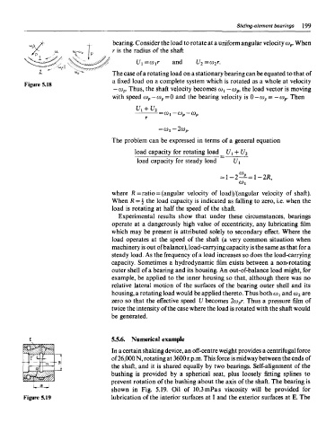
bearing. Consider the load to rotate at a uniform angular velocity o> p. When
r is the radius of the shaft
The case of a rotating load on a stationary bearing can be equated to that of
a fixed load on a complete system which is rotated as a whole at velocity
Figure 5.18
— CJ P. Thus, the shaft velocity becomes o>i — o> p, the load vector is moving
with speed (o p — co p=0 and the bearing velocity is 0 — co p= —co p. Then
The problem can be expressed in terms of a general equation
where R = ratio = (angular velocity of load)/(angular velocity of shaft).
When R = % the load capacity is indicated as falling to zero, i.e. when the
load is rotating at half the speed of the shaft.
Experimental results show that under these circumstances, bearings
operate at a dangerously high value of eccentricity, any lubricating film
which may be present is attributed solely to secondary effect. Where the
load operates at the speed of the shaft (a very common situation when
machinery is out of balance), load-carrying capacity is the same as that for a
steady load. As the frequency of a load increases so does the load-carrying
capacity. Sometimes a hydrodynamic film exists between a non-rotating
outer shell of a bearing and its housing. An out-of-balance load might, for
example, be applied to the inner housing so that, although there was no
relative lateral motion of the surfaces of the bearing outer shell and its
housing, a rotating load would be applied thereto. Thus both coi and co 2 are
zero so that the effective speed U becomes 2co pr. Thus a pressure film of
twice the intensity of the case where the load is rotated with the shaft would
be generated.
5.5.6. Numerical example
In a certain shaking device, an off-centre weight provides a centrifugal force
of 26,000 N, rotating at 3600 r.p.m. This force is midway between the ends of
the shaft, and it is shared equally by two bearings. Self-alignment of the
bushing is provided by a spherical seat, plus loosely fitting splines to
prevent rotation of the bushing about the axis of the shaft. The bearing is
shown in Fig. 5.19. Oil of 10.3 mPas viscosity will be provided for
Figure 5.19 lubrication of the interior surfaces at I and the exterior surfaces at E. The