
Page 215 - Tribology in Machine Design
P. 215
200 Tribology in machine design
diametral clearance ratio is 0.0015 at both places, and the central annular
groove at I has a width of 6 mm. Determine the load numbers and minimum
film thickness at I and E.
Solution
(i) Surface I. Relative to the load, the velocity of the bushing surface is
n\ = -3600/60= -60r.p.s. and that of the shaft is n' 2=Q. Hence,
n' = n'i+ri 2 = -60 + 0= -60r.p.s. Each bearing, carrying 26000/2
= 13 000 N, is divided by an oil groove into two effective lengths of
(75^)/2 = 34.5mm, so l/d = 34.5/50 = 0.69 and P = 13 000/2
= 6500N.
2
6
The specific load p = 6500/(34.5)(50) = 3.768 N/mm (3.768 x 10 Pa),
3
and with the oil viscosity, ^ = 10.3 x 10" Pas, the load number is
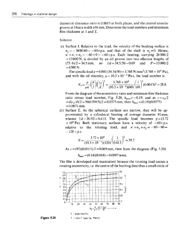
From the diagram of the eccentricity ratio and minimum film thickness
ratio versus load number, Fig. 5.20, Ji min/c = 0.19, and as c = c d/2
= d(c d/d)/2 = 50(0.0015)/2 =0.0375 mm, then fc min = (0.19)(0.0375)
= 0.0071mm.
(ii) Surface E. As the spherical surfaces are narrow, they will be ap-
proximated by a cylindrical bearing of average diameter 92mm,
whence l/d = 38/92 =0.413. The specific load becomes p = (3.72
6
x 10 Pa). Both stationary surfaces have a velocity of —60 r.p.s.
relative to the rotating load, and n' = n\+n' 2 = —6Q — 6Q =
-120 r.p.s.
The film is developed and maintained because the rotating load causes a
rotating eccentricity, i.e. the centre of the bushing describes a small circle of
Figure 5.20