
Page 264 - Tribology in Machine Design
P. 264
Rolling-contact bearings 249
explanation of the Reynolds hypothesis. In the region AC surface layers of
the rolling body are compressed in a direction along the area of contact and
elongated in the plane of the figure. In the region CB of the contact area
(a)
these deformations take place in the opposite direction, as a result of which
micro-slip occurs. Later on, this hypothesis was supplemented by experi-
mental findings which showed that slip in the contact zone is not the only
source of frictional losses during rolling. From a practical point of view, the
hypothesis that rolling friction results from the imperfect elastic properties
of engineering materials, was a significant step forward. Figure 7.2
Figure 7.1
illustrates the rationale behind this hypothesis. When a perfectly hard
roller, rolls along a yielding surface the load distribution on the roller is
unsymmetric and produces a force resisting the motion. Modern approach
to the rolling friction recognizes the fact that many factors contribute to the
total friction torque in rolling-contact bearings. Friction torque can be
expressed as follows
M = (M ds + M gr + M hs + M de + M c + M e + M m + M T)K, (7.1)
where M ds is the friction torque due to the differential slip of the rolling
Figure 7.2 element on the contact surface, M gr is the friction torque arising from
gyroscopic spin or deviation of the axis of rotation of the rolling elements,
M hs is the friction torque due to losses on elastic hysteresis in the material of
the bodies in contact, M de is the friction torque resulting from the deviation
of the bearing elements from the correct geometric shape and the micro-
roughness of contacting surfaces, M c is the friction torque due to sliding
taking place along the guide edges of the raceway and the torque arising
from the contact of the rollers with the raceway housing, M e is the friction
torque due to the shearing of a lubricant, M m is the friction torque resulting
from the working medium of the bearing (gas, liquid, air, vacuum), M T
represents a complex increase in friction torque due to an increase in
temperature and K is a correction factor taking into account complex
changes in the friction torque due to the action of forces not taken into
account when computing individual components, for example, the action of
axial and radial forces, vibrational effects, etc.
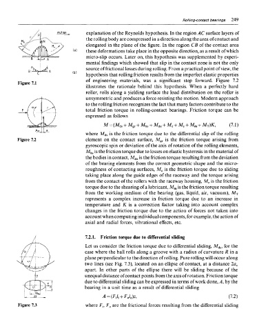
7.2.1. Friction torque due to differential sliding
Let us consider the friction torque due to differential sliding, M ds, for the
case where the ball rolls along a groove with a radius of curvature R in a
plane perpendicular to the direction of rolling. Pure rolling will occur along
two lines (see Fig. 7.3), located on an ellipse of contact, at a distance 2a c
apart. In other parts of the ellipse there will be sliding because of the
unequal distance of contact points from the axis of rotation. Friction torque
due to differential sliding can be expressed in terms of work done, A, by the
bearing in a unit time as a result of differential sliding
Figure 7.3 where F ;, F 0 are the frictional forces resulting from the differential sliding