
Page 27 - Tribology in Machine Design
P. 27
14 Tribology in machine design
from complex interactions between contacting bodies which include the
effects of surface asperity deformation, plastic gross deformation of a
weaker material by hard surface asperities or wear particles and molecular
interaction leading to adhesion at the points of intimate contact. A number
of factors, such as the mechanical and physico-chemical properties of the
materials in contact, surface topography and environment determine the
relative importance of each of the friction process components.
At a fundamental level there are three major phenomena which control
the friction of unlubricated solids:
(i) the real area of contact;
(ii) shear strength of the adhesive junctions formed at the points of real
contact;
(iii) the way in which these junctions are ruptured during relative motion.
Friction is always associated with energy dissipation, and a number of
stages can be identified in the process leading to energy losses.
Stage I. Mechanical energy is introduced into the contact zone, resulting in
the formation of a real area of contact.
Stage II. Mechanical energy is transformed within the real area of contact,
mainly through elastic deformation and hysteresis, plastic deformation,
ploughing and adhesion.
Stage III. Dissipation of mechanical energy which takes place mainly
through: thermal dissipation (heat), storage within the bulk of the body
(generation of defects, cracks, strain energy storage, plastic transform-
ations) and emission (acoustic, thermal, exo-electron generation).
2.2. Contact between Nowadays it is a standard requirement to take into account, when
bodies in relative motion analysing the contact between two engineering surfaces, the fact that they
ire covered with asperities having random height distribution and
deforming elastically or plastically under normal load. The sum of all
nicro-contacts created by individual asperities constitutes the real area of
xmtact which is usually only a tiny fraction of the apparent geometrical
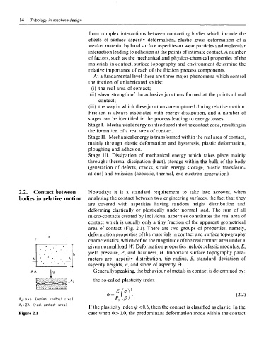
irea of contact (Fig. 2.1). There are two groups of properties, namely,
ieformation properties of the materials in contact and surface topography
:haracteristics, which define the magnitude of the real contact area under a
'iven normal load W. Deformation properties include: elastic modulus, E,
/ield pressure, P y and hardness, H. Important surface topography para-
meters are: asperity distribution, tip radius, (3, standard deviation of
isperity heights, cr, and slope of asperity 0.
Generally speaking, the behaviour of metals in contact is determined by:
the so-called plasticity index
A n= Qxb (nominal contact" area)
A r = IA; (real contact area)
If the plasticity index i/f <0.6, then the contact is classified as elastic. In the
Figure 2.1 case when i/r > 1.0, the predominant deformation mode within the contact