
Page 122 - Troubleshooting Analog Circuits
P. 122
Quashing Spurious Oscillations I09
output voltage. Putting a grid-dip oscillator nearby caused increases or decreases in
the problem, when its frequency was near 98 MHz. (Heathkit makes one of these
instruments whose updated name is “dip meter”-see Chapter 2.) At that time I
didn’t have a 100-MHz scope, but I could see the rectified envelope of these high-
frequency oscillations on a 25-MHz scope. So, if you see a circuit shift its DC level
just because you move your finger near a transistor, you should become suspicious of
high-frequency oscillations.
Of course, you will never “slide your finger around’ in a circuit with high or lethal
voltages.
One of the easiest ways to inadvertently cause a very-high-frequency oscillation is
to run an emitter-follower transistor (even a nice, docile type such as a 2N3904) at an
emitter current of 5 or 10 mA. In such a case, you can easily get an oscillation at a
few hundred megahertz. So, although a good 100-MHz scope cannot spot this kind of
oscillation, the resulting radiated noise can cause other circuits to go berserk and can
cause an entire system to fail tests for radiated electromagnetic noise.
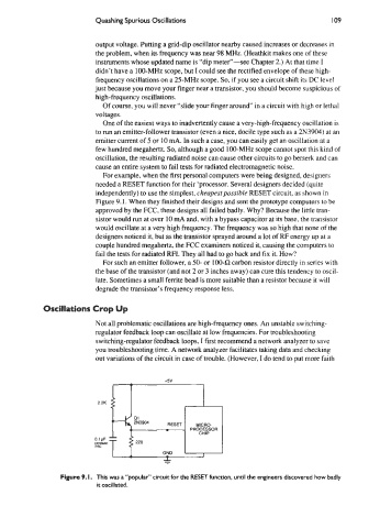
For example, when the first personal computers were being designed, designers
needed a RESET function for their ‘processor. Several designers decided (quite
independently) to use the simplest, cheupestpossible RESET circuit, as shown in
Figure 9.1. When they finished their designs and sent the prototype computers to be
approved by the FCC, these designs all failed badly. Why? Because the little tran-
sistor would run at over 10 mA and, with a bypass capacitor at its base, the transistor
would oscillate at a very high frequency. The frequency was so high that none of the
designers noticed it, but as the transistor sprayed around a lot of RF energy up at a
couple hundred megahertz, the FCC examiners noticed it, causing the computers to
fail the tests for radiated RFI. They all had to go back and fix it. How?
For such an emitter follower, a 50- or 10042 carbon resistor directly in series with
the base of the transistor (and not 2 or 3 inches away) can cure this tendency to oscil-
late. Sometimes a small femte bead is more suitable than a resistor because it will
degrade the transistor’s frequency response less.
Oscillations Crop Up
Not all problematic oscillations are high-frequency ones. An unstable switching-
regulator feedback loop can oscillate at low frequencies. For troubleshooting
switching-regulator feedback loops, I first recommend a network analyzer to save
you troubleshooting time. A network analyzer facilitates taking data and checking
out variations of the circuit in case of trouble. (However, I do tend to put more faith
2 2K
L FN3904 DCECT I ..I,.”_ I
0.lpF
CERWIC T 2 220 I I
DISC
GND I
Figure 9. I. This was a “popular” circuit for the RESET function, until the engineers discovered how badly
it oscillated.