
Page 126 - Troubleshooting Analog Circuits
P. 126
Just the Right Touch I13
circuit layout. There’s no way you can predict how much hysteresis you’ll need when
your layout changes, so you just have to re-evaluate the system after you change it.
For faster comparators, such as the LM3 11, everything gets even touchier, and the
layout is more critical. Yet, when several people accused the LM3 1 1 of being inher-
ently oscillatory, I showed them that with a good layout, the LM3 1 1 is capable of
amplifying any small signal, including its own input noise, without oscillating and
without any requirement for positive feedback. One special precaution with the
LM311 is tying the trim pins (5 and 6, normally) together to prevent AC feedback
from the output (pin 7, normally), because the trim pins can act as auxiliary inputs.
The LM3 1 1 data sheet in the National Semiconductor Linear Databook has camed a
proper set of advice and cautions since 1980, and I recommend this advice for all
comparators.
With comparators that are faster than an LM3 1 1, I find that depending on a perfect
layout alone to prevent oscillation just isn’t practical. For these comparators. you’ll
almost certainly need some hysteresis, and, if you are designing a sampled-data
system, you should investigate the techniques of strobing or latching the comparator.
Using these techniques can insure that there is no direct path from the output to the
inputs that lasts for more than just a few nanoseconds. Therefore, oscillation may be
evitable. Granted, heavy supply bypassing and a properly guarded PC-board layout,
with walls to shield the output from the input, may help. But you’ll probably still
need some hysteresis.
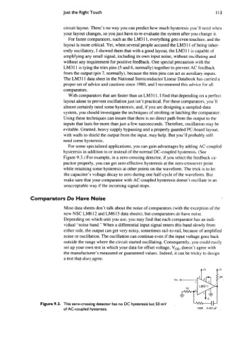
For some specialized applications, you can gain advantages by adding AC-coupled
hysteresis in addition to or instead of the normal DC-coupled hysteresis. (See
Figure 9.3.) For example, in a zero-crossing detector, if you select the feedback ca-
pacitor properly, you can get zero effective hysteresis at the zero-crossover point
while retaining some hysteresis at other points on the waveform. The trick is to let
the capacitor’s voltage decay to zero during one half-cycle of the waveform. But
make sure that your comparator with AC-coupled hysteresis doesn’t oscillate in an
unacceptable way if the incoming signal stops.
Comparators Do Have Noise
Most data sheets don’t talk about the noise of comparators (with the exception of the
new NSC LM612 and LM615 data sheets), but comparators do have noise.
Depending on which unit you use, you may find that each comparator has an indi-
vidual “noise band.” When a differential input signal enters this band slowly from
either side, the output can get very noisy, sometimes rail-to-rail, because of amplified
noise or oscillation. The oscillation can continue even if the input voltage goes back
outside the range where the circuit started oscillating. Consequently, you could easily
set up your own test in which your data for offset voltage, V,,, doesn’t agree with
the manufacturer’s measured or guaranteed values. Indeed, it can be tricky to design
a test that does agree.
Figure 9.3. This zero-crossing detector has no DC hysteresis but 50 mV
of AC-coupled hysteresis. iOOK 0001pF