
Page 177 - Troubleshooting Analog Circuits
P. 177
164 13. Letters to Bob
(b)
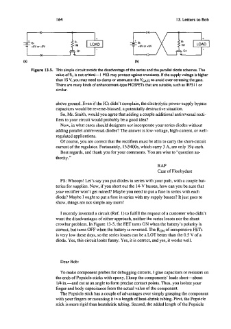
Figure 13.5. This simple circuit avoids the disadvantage of the series and the parallel diode schemes. The
value of RI is not critical-I Ma may protect against transients. If the supply voltage is higher
than I5 V, you may need to clamp or attenuate the Van to avoid over-stressing the gate.
There are many kinds of enhancement-type MOSFETs that are suitable, such as IRF5 I I or
similar.
above ground. Even if the ICs didn’t complain, the electrolytic power-supply bypass
capacitors would be reverse-biassed, a potentially destructive situation.
So, Mr. Smith, would you agree that adding a couple additional antireversal recti-
fiers to your circuit would probably be a good idea?
Now, in what cases should designers not incorporate your series diodes without
adding parallel antireversal diodes? The answer is low-voltage, high-current, or well-
regulated applications.
Of course, you are correct that the rectifiers must be able to carry the short-circuit
current of the regulator. Fortunately, 1N5400s, which carry 3 A, are only 19e each.
Best regards, and thank you for your comments. You are wise to “question au-
thority.”
RAP
Czar of Floobydust
PS: Whoops! Let’s say you put diodes in series with your path, with a couple bat-
teries for supplies. Now, if you short out the 14-V busses, how can you be sure that
your rectifier won’t get ruined? Maybe you need to put a fuse in series with each
diode? Maybe I ought to put a fuse in series with my supply busses? It just goes to
show, things are not simple any more!
I recently invented a circuit (Ref. 1) to fulfill the request of a customer who didn’t
want the disadvantages of either approach, neither the series losses nor the shunt
crowbar problem. In Figure 13-5, the FET turns ON when the battery’s polarity is
correct, but turns OFF when the battery is reversed. The RON of inexpensive FETs
is very low these days, so the series losses can be a LOT better than the 0.5 V of a
diode. Yes, this circuit looks funny. Yes, it is correct, and yes, it works well.
Dear Bob:
To make component probes for debugging circuits, I glue capacitors or resistors on
the ends of Popsicle sticks with epoxy. I keep the components’ leads short-about
1/4 in.-and cut at an angle to form precise contact points. Thus, you isolate your
finger and body capacitance from the actual value of the component.
The Popsicle stick has a couple of advantages over simply grasping the component
with your fingers or mounting it in a length of heat-shrink tubing. First, the Popsicle
stick is more rigid than heatshrink tubing. Second, the added length of the Popsicle