
Page 348 - Tunable Lasers Handbook
P. 348
308 Norman P. Barnes
4.0 0.4
h
73
E
v 3.0
0
0
r a,
m
e 0.2 0
Q
e 2.0
z
1 .o 0.1
0 Threshold
Slope efficiency
0 50 100 150
Resonator length (rnm)
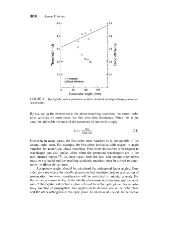
FIGURE 5 The AgGaSe2 optical parametric oscillator threshold and slope efficiency versus res-
onator length.
By evaluating the expression at the phase-matching condition, the zeroth-order
term vanishes. In most cases, the first term then dominates. When this is the
case, the allowable variance of the parameter of interest is simply
However, in many cases, the first-order term vanishes or is comparable to the
second-order term. For example, the first-order derivative with respect to angle
vanishes for noncritical phase matching. First-order derivatives with respect to
wavelength can also vanish, often when the generated wavelengths are in the
mid-infrared region [7]. In these cases, both the first- and second-order terms
must be evaluated and the resulting quadratic equation must be solved to deter-
mine the allowable variance.
Acceptance angles should be calculated for orthogonal input angles. Con-
sider the case where the ideally phase-matched condition defines a direction of
propagation. For now, consideration will be restricted to uniaxial crystals. For
the situation shown in Fig. 6 the ideally phase-matched direction and the optic
axis of the crystal will define a plane referred to as the optic plane. For an arbi-
trary direction of propagation, two angles can be defined, one in the optic plane
and the other orthogonal to the optic plane. In an uniaxial crystal, the refractive