
Page 405 - Tunable Lasers Handbook
P. 405
8 Tunable External-Cavity Semiconductor Lasers 365
also helps reduce nonradiative losses due to Auger recombination, which is a
potential problem for lasers at h > 1 pm. Typical MQW devices have four to five
wells. A basic introduction to the physics of quantum-well lasers is given in the
textbook by Yariv [13]. A much more detailed treatment can be found in the arti-
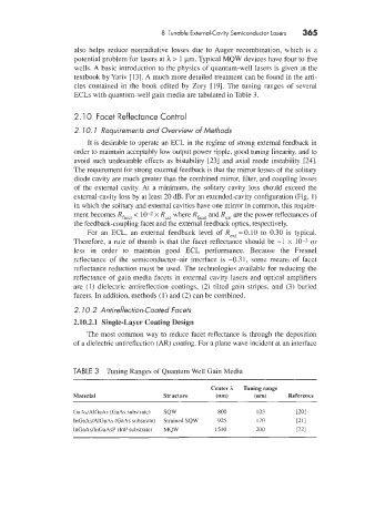
cles contained in the book edited by Zory [19]. The tuning ranges of several
ECLs with quantum-well gain media are tabulated in Table 3.
2.10 Facet Reflectance Control
7
2. IO. Requirements and Overview of Methods
It is desirable to operate an ECL in the regime of strong external feedback in
order to maintain acceptably low output power ripple. good tuning linearity, and to
avoid such undesirable effects as bistability [23] and axial mode instability [24].
The requirement for strong external feedback is that the mirror losses of the solitary
diode cavity are much greater than the combined mirror, filter, and coupling losses
of the external cavity At a minimum, the solitary cavity loss should exceed the
external-cavity loss by at least 30 dB. For an extended-cavity configuration (Fig. 1)
in which the solitary and external cavities have one mirror in common, this require-
ment becomes Rfacst < 10-2 x Rex[ where Rfaca and Rexr are the power reflectances of
the feedback-coupling facet and the external feedback optics, respectively.
For an ECL, an external feedback level of ReXt = 0.10 to 0.30 is typical.
Therefore, a rule of thumb is that the facet reflectance should be -1 x 10⁻³ or
less in order to maintain good ECL performance. Because the Fresnel
reflectance of the semiconductor-air interface is -0.31, some means of facet
reflectance reduction must be used. The technologies available for reducing the
reflectance of gain media facets in external cavity lasers and optical amplifiers
are (I) dielectric antireflection coatings, (2) tilted gain stripes, and (3) buried
facets. In addition, methods (1) and (2) can be combined.
2. 7 0.2 Antireflection-Coated Facets
2.10.2.1 Single-Lager Coating Design
The most common way to reduce facet reflectance is through the deposition
of a dielectric antireflection (AR) coating. For a plane wave incident at an interface
TABLE 3 Tuning Ranges of Quantum Well Gain Media
Center h Tuning range
Material Structure (nm) (nmJ Reference
GaAs/r\lGai\s (GaAs substrate J SQW 800 105 POI
InGaAs/AlGaAs (GaAs substrate) Strained SQW 925 170 r211
InGaAdInGaAsP (InP substrate) MQW 1540 200 [22]