
Page 447 - Tunable Lasers Handbook
P. 447
8 Tunable External-Cavity Semiconductor Lasers 407
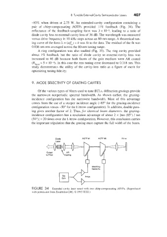
-85% when driven at 2.75 W. An extended-cavity configuration containing a
pair of chirp-compensating AOTFs provided 11% feedback (Fig. 34). The
reflectance (of the feedback-coupling facet was 3 x 10⁻⁵, leading to a ratio of
diode cavity loss to external-cavity loss of 36 dB. The wavelength was measured
versus drive frequency in 10-kHz steps across an 80-nm range. A theoretical tun-
ing curve of the form h = (aFa ) + b was fit to the data. The residual of the fit was
0.036 nm rms averaged across the 80-nm tuning range.
A ring configuration was also studied (Fig. 35). The ring cavity provided
about 1% feedback but the ratio of diode cavity to external-cavity loss was
increased to 46 dB because both facets of the gain medium were AR coated
(Ria,,, = 5 x 10⁻⁴). In this case the rms tuning error decreased to 0.1318 nm. This
study demonstrates the utility of the cavity-loss ratio as a figure of merit for
optimizing tuning fidelity.
9. MODE SELECTIVITY OF GRATING CAVITIES
Of the various types of filters used to tune ECLs, diffraction gratings provide
the narrowest nonperiodic spectral bandwidth. As shown earlier, the grazing-
incidence configuration has the narrowest bandwidth. Most of this advantage
comes from the use of a steeper incidence angle (-85O for the grazing-incidence
configuration versus -50" for the Littrow configuration). In addition, double pass-
ing gives another factor of 2. Thus, for iderztical beam diameters. the grazing-
incidence configuration has a resolution advantage of about 2 x [tan (85") / tan
(50")] = 20 times over the Littrow configuration. However, this conclusion carries
the important stipulation that the grating must capture the full midth of the beam.
Diode AOTF #1 AOTF #2 Mirror
$ I
Laser
______--- ----___
----_____ ___----
FIGURE 34 Extended cavity laser tuned with two chirpcompensating AOTFs. (Reproduced
with permission from Zorabedian [46]. 0 1995 IEEE.)