
Page 448 - Tunable Lasers Handbook
P. 448
408 Paul Zorabedian
..
..
\ .. ..
..
..
lo Fiber
..
..
..
..
..
..
..
..
??. Amplifier AOTF #2 ..
Optical
Matching AR Coatings Matching
Network
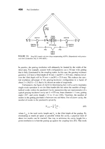
FIGURE 35 Ring ECL tuned with two chirp-compensating AOTFs. (Reproduced with Fermis-
sion from Zorabedian [46]. 0 1995 IEEE.)
In practice, the grating resolution will ultimately be limited by the width of the
ruled area. For example, assume both configurations use a 30-mm wide grating
that is fully illuminated by the coupling optics. In this case, the grazing-incidence
geometry will have a filled depth of 30 mm x sin(85") = 29.9 mm, whereas in Lit-
trow the filled depth will be 30 mm x sin(50") = 23.0 mm. This reduces the spec-
tral resolution advantage of the grazing-incidence configuration to a factor of
about 2 x (30/23) = 2.5, that is, by almost an order of magnitude.
Furthermore, the figure of merit for determining how well a cavity maintains
single-mode operation is not the filter bandwidth but rather the number of longi-
tudinal modes within the passband. Cavity parameters that are representative of a
typical grazing-incidence cavity are h = 670 nm, beam diameter = 1 mm, grating
angle = 85", and cavity length = 7.5 to 15 cm [105]. Therefore, the number of
modes in the grating passband is between one and three. For a Littrow cavity, the
number of modes in the passband is given by
where Leal, is the total cavity length and Lg is the filled depth of the grating. By
eliminating as much air space as possible within the cavity, a practical limit of
about two modes can be reached. One way to minimize the cavity length for a
given resolution is to butt the grating up against the coupling lens [SI. This tends