
Page 355 - Understanding Automotive Electronics
P. 355
2735 | CH 10 Page 342 Tuesday, March 10, 1998 1:27 PM
10 DIAGNOSTICS
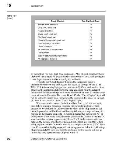
Table 10.1
(cont.)
Circuit Affected Two-Digit Fault Code
Throttle switch circuit test 72
Drive (ADL) circuit test 73
Reverse circuit test 74
Cruise on/off circuit test 75
“Set/Coast” circuit test 76
“Resume/Acceleration” circuit test 77
“Instant/Average” circuit test 78
“Reset” circuit test 79
Air conditioner clutch circuit test 80
Display check 88
System ready to display engine data 90
All diagnostics complete 00
an example of two-digit fault code assignment. After all fault codes have been
displayed, the number 70 appears on the climate control head, and the engine
control system awaits further action by the mechanic.
Typically, the “Check Engine” light on the instrument panel is
illuminated whenever any fault occurs. For codes 12 through 38 and 51 in
Table 10.1, this warning light goes out automatically if the malfunction clears.
However, the control module stores the code associated with the detected
failure until the diagnostic system is manually cleared, or until 20 engine cycles
occur with no malfunction. For codes 44 and 45, the “Check Engine” light will
not go out until cleared from memory by the mechanic. For codes 60 through
68, there is no activation of the “Check Engine” light.
Whenever a defect occurs (as indicated by a fault code), the mechanic
must follow a specific procedure to isolate the particular problem. These
procedures are outlined for the mechanic in charts in the shop manuals. An
example procedure will be illustrated here by following the steps necessary to
respond to the specific fault code 13, which indicates that the oxygen (O or
2
EGO) sensor is not ready. Recall from the discussion in Chapter 6 that the O
2
sensor switches between approximately 0 and 1 volt as the mixture switches
between the extreme conditions of lean and rich. Recall also that this voltage
swing requires that the O sensor must be at a temperature above 200˚C. Fault
2
code 13 means that the O sensor will not swing above or below its cold voltage
2
of approximately 0.5 volt, and that the electronic control system will not go
into closed-loop operation (see Chapters 5 and 7).
342 UNDERSTANDING AUTOMOTIVE ELECTRONICS