
Page 359 - Understanding Automotive Electronics
P. 359
2735 | CH 10 Page 346 Tuesday, March 10, 1998 1:27 PM
10 DIAGNOSTICS
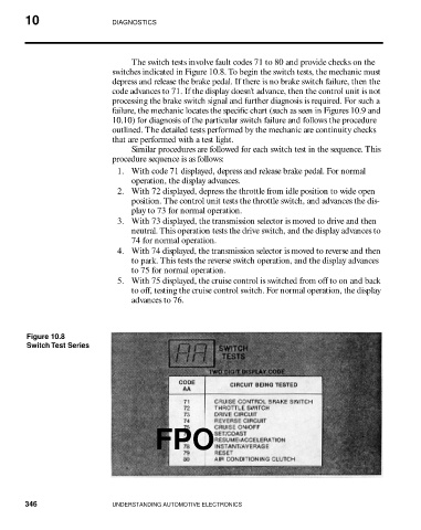
The switch tests involve fault codes 71 to 80 and provide checks on the
switches indicated in Figure 10.8. To begin the switch tests, the mechanic must
depress and release the brake pedal. If there is no brake switch failure, then the
code advances to 71. If the display doesn’t advance, then the control unit is not
processing the brake switch signal and further diagnosis is required. For such a
failure, the mechanic locates the specific chart (such as seen in Figures 10.9 and
10.10) for diagnosis of the particular switch failure and follows the procedure
outlined. The detailed tests performed by the mechanic are continuity checks
that are performed with a test light.
Similar procedures are followed for each switch test in the sequence. This
procedure sequence is as follows:
1. With code 71 displayed, depress and release brake pedal. For normal
operation, the display advances.
2. With 72 displayed, depress the throttle from idle position to wide open
position. The control unit tests the throttle switch, and advances the dis-
play to 73 for normal operation.
3. With 73 displayed, the transmission selector is moved to drive and then
neutral. This operation tests the drive switch, and the display advances to
74 for normal operation.
4. With 74 displayed, the transmission selector is moved to reverse and then
to park. This tests the reverse switch operation, and the display advances
to 75 for normal operation.
5. With 75 displayed, the cruise control is switched from off to on and back
to off, testing the cruise control switch. For normal operation, the display
advances to 76.
Figure 10.8
Switch Test Series
FPO
346 UNDERSTANDING AUTOMOTIVE ELECTRONICS