Page 86 - Understanding Automotive Electronics
P. 86

2735 | CH 3  Page 73  Tuesday, March 10, 1998  11:03 AM


                                         ELECTRONICS FUNDAMENTALS                                          3
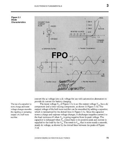


                    Figure 3.1
                    Diode
                    Characteristics


                                                         FPO


                                         convert the ac voltage into a dc voltage for use with automotive alternators to
                                         provide dc current for battery charging.
                    The use of a capacitor to   The input voltage V  of Figure 3.1c is ac; the output voltage V  has a dc
                                                               in
                                                                                                   out
                    store charge and resist   component and a time-varying component, as shown in Figure 3.1d. The
                    voltage changes smooths   output voltage of the half-wave rectifier can be smoothed by adding a capacitor,
                    the rippling or pulsating   which is represented by the dotted lines in Figure 3.1c. Since the capacitor
                    output of a half-wave   stores a charge and opposes voltage changes, it discharges (supplies current) to
                    rectifier.            the load resistance R when V  is going negative from its peak voltage. The
                                                                  in
                                         capacitor is recharged when V  comes back to its positive peak and current is
                                                                  in
                                         supplied to the load by the V . The result is V  that is more nearly a smooth,
                                                                  in
                                                                                out
                                         steady dc voltage, as shown by the dotted lines between the peaks of Figure
                                         3.1d.


                                         UNDERSTANDING AUTOMOTIVE ELECTRONICS                             73
   81   82   83   84   85   86   87   88   89   90   91