
Page 145 - Understanding Flight
P. 145
CH05_Anderson 7/25/01 8:58 AM Page 132
132 CHAPTER FIVE
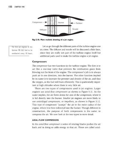
Compressor Burner Turbine
Diffuser Nozzle
Fig. 5.10. More realistic drawing of a jet engine.
The first jet engines in the Let us go through the different parts of the turbine engine one
German ME-262 had to be at a time. The diffuser and nozzle will be discussed a little later,
overhauled every 10 hours. since they are really not part of the turbine engine itself but
additional parts used to make the turbine engine a jet engine.
Compressors
The compressor has two functions in the turbine engine. The first is to
act like a one-way valve that prevents the combustion gases from
blowing out the front of the engine. The compressor’s job is to always
push air in one direction, into the burner. The other function implied
by its name is to increase the pressure and density of the air, and thus
the oxygen, so the fuel will burn efficiently. This is particularly impor-
tant at high altitudes where there is very little air.
There are two types of compressors used in jet engines. Larger
engines use axial-flow compressors as shown in Figure 5.11. As the
name implies, the air flows down the axis of the compressor, where it
is fed directly into the burner. Smaller jet engines are more likely to
use centrifugal compressors, or impellers, as shown in Figure 5.12.
This type of compressor “pumps” the air to the outer radius of the
engine, where it is then redirected into the burner. Though different in
construction, the purpose of both compressors is the same: to
compress the air. We now look at the two types in more detail.
AXIAL-FLOW COMPRESSORS
In the axial-flow compressor a series of rotating blades pushes the air
back and in doing so adds energy to that air. These are called axial-