
Page 149 - Understanding Flight
P. 149
CH05_Anderson 7/25/01 8:58 AM Page 136
136 CHAPTER FIVE
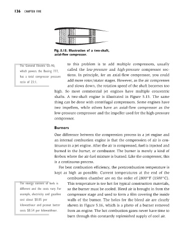
Fig. 5.15. Illustration of a two-shaft,
axial-flow compressor.
to this problem is to add multiple compressors, usually
The General Electric GE-90,
called the low-pressure and high-pressure compressor sec-
which powers the Boeing 777,
tions. In principle, for an axial-flow compressor, you could
has a total compressor pressure
add more rotor/stator stages. However, as the air compresses
ratio of 23:1.
and slows down, the rotation speed of the shaft becomes too
high. So most commercial jet engines have multiple concentric
shafts. A two-shaft engine is illustrated in Figure 5.15. The same
thing can be done with centrifugal compressors. Some engines have
two impellers, while others have an axial-flow compressor as the
low-pressure compressor and the impeller used for the high-pressure
compressor.
Burners
One difference between the compression process in a jet engine and
an internal combustion engine is that the compression of air is con-
tinuous in a jet engine. After the air is compressed, fuel is injected and
burned in the burner, or combustor. The burner is merely a kind of
firebox where the air-fuel mixture is burned. Like the compressor, this
is a continuous process.
For best combustion efficiency, the postcombustion temperature is
kept as high as possible. Current temperatures at the end of the
combustion chamber are on the order of 2800°F (1500°C).
The energy content of fuels is This temperature is too hot for typical construction materials,
different and the costs vary. For so the burner must be cooled. Bleed air is brought in from the
example, electricity and gasoline compressor stage and used to form a film covering the inside
cost about $0.05 per walls of the burner. The holes for the bleed air are clearly
kilowatthour and peanut butter shown in Figure 5.16, which is a photo of a burner removed
costs $0.54 per kilowatthour. from an engine. The hot combustion gases never have time to
burn through this constantly replenished supply of cool air.