
Page 154 - Understanding Flight
P. 154
CH05_Anderson 7/25/01 8:58 AM Page 141
Airplane Propulsion 141
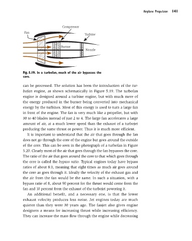
Compressor
Fan
Turbine
Burner
Nozzle
Fig. 5.19. In a turbofan, much of the air bypasses the
core.
can be processed. The solution has been the introduction of the tur-
bofan engine, as shown schematically in Figure 5.19. The turbofan
engine is designed around a turbine engine, but with much more of
the energy produced in the burner being converted into mechanical
energy by the turbines. Most of this energy is used to turn a large fan
in front of the engine. The fan is very much like a propeller, but with
30 to 40 blades instead of just 2 to 4. The large fan accelerates a large
amount of air, at a much lower speed than the exhaust of a turbojet
producing the same thrust or power. Thus it is much more efficient.
It is important to understand that the air that goes through the fan
does not go through the core of the engine but goes around the outside
of the core. This can be seen in the photograph of a turbofan in Figure
5.20. Clearly most of the air that goes through the fan bypasses the core.
The ratio of the air that goes around the core to that which goes through
the core is called the bypass ratio. Typical engines today have bypass
ratios of about 8:1, meaning that eight times as much air goes around
the core as goes through it. Ideally the velocity of the exhaust gas and
the air from the fan would be the same. In such a situation, with a
bypass ratio of 8, about 90 percent for the thrust would come from the
fan and 10 percent from the exhaust of the turbojet powering it.
An additional benefit, and a necessary one, is that the lower
exhaust velocity produces less noise. Jet engines today are much
quieter than they were 30 years ago. The fanjet also gives engine
designers a means for increasing thrust while increasing efficiency.
They can increase the mass flow through the engine while decreasing