
Page 162 - Uninterruptible Power Supplies
P. 162
Static Uninterruptible Power Supplies
160 Chapter Five
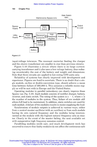
Main Switch
Maintenance Bypass Line SW1
Bypass Static Output
Supply Switch to Load
High
Utility Input Resonant
Supply Rectifier Converter Frequency Inverter
Rectifier
Battery
Charger
Battery
Figure 5.17
input-voltage tolerance. The resonant converter feeding the charger
and the shown transformer are smaller in size than previous circuits.
Figure 5.18 illustrates a circuit where there is no large current-
carrying transformer and it also uses a low-voltage battery, thus reduc-
ing considerably the cost of the battery and weight and dimensions.
Note that these circuits are applied to low-rating UPS units only.
Reliability of systems has clearly improved with development and
experience. Figures are hard to ascertain. There is no doubt that a sin-
gle module, on-line or double-conversion type, should achieve a mean
time between failure of 260,000 h. This assumes a reliable mains sup-
ply as will be met with in Europe and the United States.
Operating modules in parallel redundancy can clearly improve these
figures (see Fig. 5.19). Each module consists of rectifier charger, battery,
inverter, and static switch. The rating of the system is n 1, where n is
the number of modules in the system. Thus, failure of one module still
allows full load to be maintained. In addition, static switches are used for
each module. Afailure of two modules results in mains supplying the load.
Synchronism of module outputs is achieved in various ways, either
from a central master oscillator with an auxiliary or from each module
having its own natural frequency and the modules being intercon-
nected so the module with the highest natural frequency acts as mas-
ter. Clearly in the event of the master failing, the next available set
with comparative high frequency assumes control.
Paralleling modules needs care, and much development work has
occurred to ensure that faulty modules do not affect the continuous safe
Downloaded from Digital Engineering Library @ McGraw-Hill (www.digitalengineeringlibrary.com)
Copyright © 2004 The McGraw-Hill Companies. All rights reserved.
Any use is subject to the Terms of Use as given at the website.