
Page 164 - Uninterruptible Power Supplies
P. 164
Static Uninterruptible Power Supplies
162 Chapter Five
UPS NR. 1
~ – ~ ~
– + ~ ~
UPS NR. 2
~ –
MAINS ~ ~
INPUT – + ~ ~ OUT
UPS NR. _ _
~ – ~ ~
– + ~ ~
AUXILIARY
MAINS
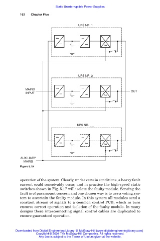
Figure 5.19
operation of the system. Clearly, under certain conditions, a heavy fault
current could conceivably occur, and in practice the high-speed static
switches shown in Fig. 5.17 will isolate the faulty module. Sensing the
fault is of paramount concern and one chosen way is to use a voting sys-
tem to ascertain the faulty module. In this system all modules send a
constant stream of signals to a common control PCB, which in turn
ensures correct operation and isolation of the faulty module. In many
designs these interconnecting signal control cables are duplicated to
ensure guaranteed operation.
Downloaded from Digital Engineering Library @ McGraw-Hill (www.digitalengineeringlibrary.com)
Copyright © 2004 The McGraw-Hill Companies. All rights reserved.
Any use is subject to the Terms of Use as given at the website.