
Page 17 - Uninterruptible Power Supplies
P. 17
Standby Power Generating Sets
Standby Power Generating Sets 15
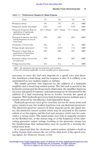
TABLE 1.1 Performance Classes for Diesel Engines
Class G1 G2 G3 G4
Frequency droop 8% 5% 3% AMC
Frequency steady state band 2.5% 1.5% 0.5% AMC
Transient frequency drop on 15% droop 10% droop 7% droop AMC
application of maximum
permitted step load
Transient frequency rise from 18% 12% 10% AMC
initial frequency on loss of
rated load
Frequency recovery time 10 s 5 s 3 s AMC
Voltage steady state band 5% 2.5% 1% AMC
Transient voltage drop on 25% 20% 15% AMC
application of maximum
permitted step load
Transient voltage rise on loss 35% 25% 20% AMC
of rated load
Voltage recovery time 10 s 6 s 4 s AMC
AMC By agreement between manufacturer and customer.
Class G3 would be applicable to most standby power applications.
necessary to move the fuel rack depends on a speed error and there-
fore introduces a load droop, and the response is slow. It is unlikely to be
encountered on any modern engine or turbine.
The simple governor was improved by the addition of a hydraulic
amplifier and a closed loop control system. The fuel rack is moved by the
hydraulic system and the droop can be eliminated, the amplifier improves
accuracy and speed of response, and load sensing can be introduced by the
addition of a load measuring device to further increase the speed of
response. With hydraulic governors load sharing between multiple sets is
usually achieved by introducing a load-dependent droop.
Hydraulic governors have given excellent service for many years and
many remain in use, but modern machines now use electronic governors.
The electronic governor consists of three separate parts, the speed sen-
sor, the electronic control system which may be mounted in the control
cubicle or on the engine, and the fuel rack actuator which may be a sole-
noid or a torque motor. The speed sensor may look at magnetic markers
on the flywheel rim, at the starter ring, or at the frequency of the alter-
nating generator output voltage. Looking at the generator output has
the disadvantage that maloperation may be caused by a severely dis-
torted wave form.
It is important that the electronic control system includes a built-in
safety feature that ensures the set will be shut down if the speed sens-
ing signal, for whatever reason, is lost.
Downloaded from Digital Engineering Library @ McGraw-Hill (www.digitalengineeringlibrary.com)
Copyright © 2004 The McGraw-Hill Companies. All rights reserved.
Any use is subject to the Terms of Use as given at the website.