
Page 18 - Uninterruptible Power Supplies
P. 18
Standby Power Generating Sets
16 Chapter One
Electronic governors make it easy to change the control parameters
within the feedback loop and to send or receive electrical analogue sig-
nals. Functions such as load sharing, load management, and automatic
synchronizing are easier than with hydraulic governors. Load sharing
between paralleled sets is achieved by interconnecting a load share sig-
nal to each governor, if one machine is taking too great a share of load
the sharing signal will react to reduce its fuel supply.
Early electronic governors used analogue systems which compared
the measured quantity with the set value and made any necessary cor-
rections to the fuel rack position. Modern governors use digital systems
which digitize the measured and set values and feed the results into a
processor which determines any corrections to be made to the fuel rack
position. Digital systems are more versatile than analogue, changes to
the operating parameters or sequence can often be achieved by a soft-
ware adjustment instead of having to undertake a hardware modifica-
tion. For the simplest applications digital systems have no particular
advantages, but they may well become the normal manufacturing stan-
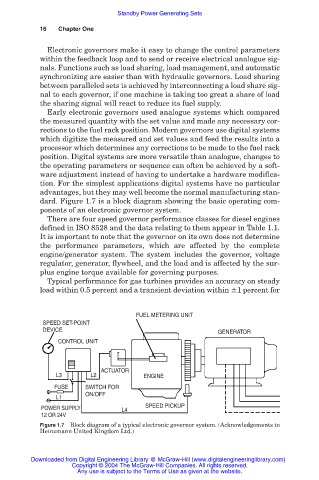
dard. Figure 1.7 is a block diagram showing the basic operating com-
ponents of an electronic governor system.
There are four speed governor performance classes for diesel engines
defined in ISO 8528 and the data relating to them appear in Table 1.1.
It is important to note that the governor on its own does not determine
the performance parameters, which are affected by the complete
engine/generator system. The system includes the governor, voltage
regulator, generator, flywheel, and the load and is affected by the sur-
plus engine torque available for governing purposes.
Typical performance for gas turbines provides an accuracy on steady
load within 0.5 percent and a transient deviation within 1 percent for
FUEL METERING UNIT
SPEED SET-POINT
DEVICE GENERATOR
CONTROL UNIT
ACTUATOR
L3 L2 ENGINE
FUSE SWITCH FOR
ON/OFF
L1
POWER SUPPLY L4 SPEED PICKUP
12 OR 24V
Figure 1.7 Block diagram of a typical electronic governor system. (Acknowledgements to
Heinzmann United Kingdom Ltd.)
Downloaded from Digital Engineering Library @ McGraw-Hill (www.digitalengineeringlibrary.com)
Copyright © 2004 The McGraw-Hill Companies. All rights reserved.
Any use is subject to the Terms of Use as given at the website.