
Page 227 - Uninterruptible Power Supplies
P. 227
Kinetic Energy as an Alternative Power Source
Kinetic Energy as an Alternative Power Source 225
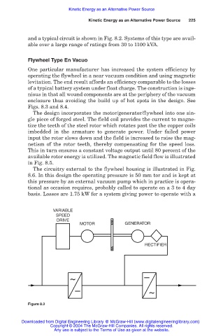
and a typical circuit is shown in Fig. 8.2. Systems of this type are avail-
able over a large range of ratings from 30 to 1100 kVA.
Flywheel Type En Vacuo
One particular manufacturer has increased the system efficiency by
operating the flywheel in a near vacuum condition and using magnetic
levitation. The end result affords an efficiency comparable to the losses
of a typical battery system under float charge. The construction is inge-
nious in that all wound components are at the periphery of the vacuum
enclosure thus avoiding the build up of hot spots in the design. See
Figs. 8.3 and 8.4.
The design incorporates the motor/generator/flywheel into one sin-
gle piece of forged steel. The field coil provides the current to magne-
tize the teeth of the steel rotor which rotates past the the copper coils
imbedded in the armature to generate power. Under failed power
input the rotor slows down and the field is increased to raise the mag-
netism of the rotor teeth, thereby compensating for the speed loss.
This in turn ensures a constant voltage output until 80 percent of the
available rotor energy is utilized. The magnetic field flow is illustrated
in Fig. 8.5.
The circuitry external to the flywheel housing is illustrated in Fig.
8.6. In this design the operating pressure is 50 mm tor and is kept at
this pressure by an external vacuum pump which in practice is opera-
tional as occasion requires, probably called to operate on a 3 to 4 day
basis. Losses are 1.75 kW for a system giving power to operate with a
VARIABLE
SPEED
DRIVE
MOTOR GENERATOR
RECTIFIER
~ –
– ~
Figure 8.2
Downloaded from Digital Engineering Library @ McGraw-Hill (www.digitalengineeringlibrary.com)
Copyright © 2004 The McGraw-Hill Companies. All rights reserved.
Any use is subject to the Terms of Use as given at the website.