
Page 213 - Urban Construction Project Management
P. 213
168 Chapter Seven
Exhibit 7-5
Site layout
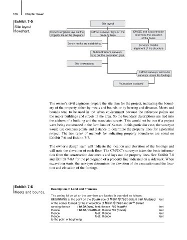
Site layout
flowchart. Owner’s engineer lays out the CM/GC surveyor lays out the CM/GC and subcontractor
property line on the site plans property lines determine the elevation
of the floors
Bench marks are established
Surveyor checks
alignment of the structure
Subcontractor’s surveyor
lays out the excavation plan
Site is excavated
CM/GC surveyor and subs
surveyor locate the footings
Foundation is placed
The owner’s civil engineers prepare the site plan for the project, indicating the bound-
ary of the property either by meets and bounds or by bearing and distance. Meets and
bounds tend to be used in the urban environment because the reference points are
the major buildings and streets in the area. So the boundary descriptions are tied into
the address of a building and the associated streets. This would not be true if a project
were being constructed in the farm land of Kansas. In this particular case, the surveyor
would use compass points and distance to determine the property lines for a potential
project. The two types of methods for indicating property boundaries are noted on
Exhibit 7-6 and Exhibit 7-7.
The owner’s design team will indicate the location and elevation of the footings and
will note the elevation of each floor. The CM/GC’s surveyor takes the basic informa-
tion from the construction documents and lays out the property lines. See Exhibit 7-8
and Exhibit 7-8A for the photograph of a property line indicated on a sidewalk. When
excavation starts, the surveyor determines the elevation of the excavation and the loca-
tion and elevation of the footings.
Exhibit 7-6
Description of Land and Premises
Meets and bounds.
The zoning lot on which the premises are located is bounded as follows:
BEGINNING at the point on the South side of Main Street distant 150.10 (East) feet
th
of the corner formed by the intersection of Main Street and 57 Street
running thence 110.50 (east) feet; thence 100 (south) feet
thence 110.50 (west) feet; thence100 (north) feet
thence feet; thence feet
thence feet; thence feet
to the point of beginning.