
Page 105 - Using ANSYS for Finite Element Analysis A Tutorial for Engineers
P. 105
92 • Using ansys for finite element analysis
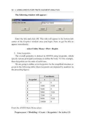
The following window will appear:
Enter the title and click OK. This title will appear in the bottom-left
corner of the Graphics window once you begin. Note: to get the title to
appear immediately,
select Utility Menu > Plot > Replot
2. Enter keypoints.
The overall geometry is defined in ANSYS using keypoints, which
specify various principal coordinates to define the body. For this example,
these keypoints are the ends of each truss.
We are going to define seven keypoints for the simplified structure as
given in the following table (these keypoints are depicted by numbers in
the preceding figure).
Coordinate
keypoint x y
1 0 0
2 1800 3118
3 3600 0
4 5400 3118
5 7200 0
6 9000 3118
7 10800 0
From the ANSYS Main Menu select:
Preprocessor > Modeling > Create > Keypoints > In Active CS