
Page 219 -
P. 219
Chapter 5 Database Processing
218
• Represent each entity with a table
– Entity identifier becomes table key
– Entity attributes become table columns
• Normalize tables as necessary
• Represent relationships
Figure 5-25 – Use foreign keys
Transforming a Data Model into a – Add additional tables for N:M relationships
Database Design
resulting tables are normalized so that each table has a single theme. Once that has been done, the
next step is to represent relationship among those tables.
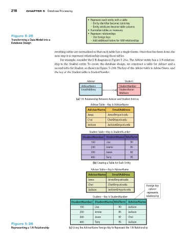
For example, consider the E-R diagram in Figure 5-26a. The Adviser entity has a 1:N relation-
ship to the Student entity. To create the database design, we construct a table for Adviser and a
second table for Student, as shown in Figure 5-26b. The key of the Adviser table is AdviserName, and
the key of the Student table is StudentNumber.
Adviser Student
AdviserName StudentNumber
EmailAddress StudentName
MidTerm
(a) 1:N Relationship Between Adviser and Student Entities
Adviser Table—Key Is AdviserName
AdviserName EmailAddress
Jones Jones@myuniv.edu
Choi Choi@myuniv.edu
Jackson Jackson@myuniv.edu
Student Table—Key Is StudentNumber
StudentNumber StudentName MidTerm
100 Lisa 90
200 Jennie 85
300 Jason 82
400 Terry 95
(b) Creating a Table for Each Entity
Adviser Table—Key Is AdviserName
AdviserName EmailAddress
Jones Jones@myuniv.edu
Choi Choi@myuniv.edu Foreign key
Jackson Jackson@myuniv.edu column
represents
Student—Key Is StudentNumber relationship
StudentNumber StudentName MidTerm AdviserName
100 Lisa 90 Jackson
200 Jennie 85 Jackson
300 Jason 82 Choi
400 Terry 95 Jackson
Figure 5-26
Representing a 1:N Relationship (c) Using the #FXKUGT0COG Foreign Key to Represent the 1:N Relationship